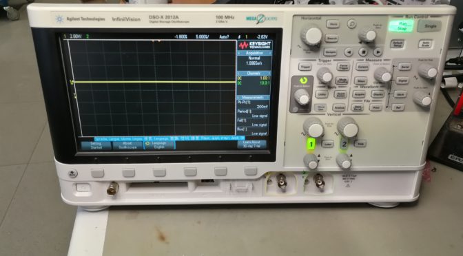
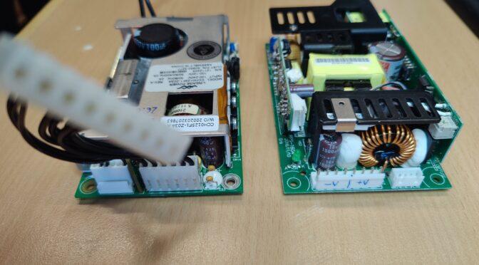
Speech output in the 80s – Speak and Spell

Loading

Many of the readers of this post may be familiar with the Hollywood movie E.T. (The Extra-Terrestrial), in our regions in the translated version: “E.T. – Der Außerirdische”.

At least the older readers will know him. The film was shown in our cinemas in 1982 and I had the opportunity to see it at the time. As a child, you (at least I) always immersed yourself in the stories and lived in them. Briefly told, the story follows a small alien who was accidentally left behind on Earth while his fellow aliens flew away in their spaceship, fleeing from government agents. So little E.T. in a shed where he was found by local children. They befriended him and helped him contact the spaceship. To do this, he constructed a kind of radio system from everyday objects. For example, the antenna consisted of an umbrella, a record player with a circular saw blade, a clothes hanger with a dinner fork, and a child’s toy that could produce synthetic voices. This toy is called “Speak & Spell” and was developed by the Texas Instruments company.

The Speak & Spell is a handheld children’s computer from TI (Texas Instruments) that consists of a keyboard, a display and a small speaker. The heart of the device is a speech synthesizer IC, which makes it possible to generate an artificial voice. An audio output similar to the human speaking voice is achieved via LPC (linear predictive coding). With an internal ROM and optionally also external ROM modules, various tasks (spelling, word guessing games, etc.) can be realized. Selection and entry are made via a keyboard.

The Speak & Spell children’s computer originally came from a three-part toy series with “talking” computers. There was also a Speak & Math and a Speak & Read. You can occasionally find collectors presenting their devices on online video platforms. The devices were initially sold in the USA, Great Britain and Japan. Depending on the country of delivery, there were also different ROM modules with mini-games such as Mystery Word, Letter or Secret Code. These computers were intended for children from the age of 7. Later, more language libraries were released in seven language variations. Among other things, there is said to have been a module for the German language.

The first Speak & Spell was introduced at the 1978 Consumer Electronics Show as one of the first portable devices with a visual display and pluggable ROM game cartridges. This model was also used in the film E.T. known. It differs from later generations of devices only in terms of the keyboard, which in the original version still consisted of “real” keys. The TMC0280 synthesizer chip works inside. This was developed by a small team of engineers under Paul Breedlove † (1941-2021), engineer at Texas Instruments in the late 1970’s. This development began in 1976 as a result of TI research on speech synthesis.

At the beginning of the 1980s, a revised version of the device came onto the market. Here the keys have been replaced by a membrane keyboard. A Speak & Spell Compact version has also been released. In this case, the optical VFD display has been dispensed with and the size has been halved. There was another edition in the late 1980s. This time the VFD was replaced by an LC display and the keyboard got a QWERTY layout. As part of the retro wave (my guess) the company “Basic Fun” brought the classic Speak&Spell back onto the market in 2019. It looks similar to the 80s version, but is technically up to date (everything is generated in a small chip that was bonded directly to the “mini board”). The version also no longer has connections to the outside world.

The following chips are installed on the mainboard of the version sold before 1980:

  • TMC0271 (microcontroller and VF display controller for 9 digits with 14 segments each)
  • TMC0530 (or TMC0351, TMC0352) 128kBit ROM
  • TMC0281 (TMC0280 series speech synthesizer IC)


The model that is in my collection is one of the versions sold after 1980. The following ICs are installed here:

  • TMC0271 (microcontroller and VF display controller for 9 digits with 14 segments each)
  • TMC0281 (TMC0280 Series Speech Synthesizer IC)
  • CD2304 and CD2303 (ROM)


The VF-display has eight digits with 14 segments each. The supply voltage of 6V is obtained from four C-cells connected in series. The 9V and 21V for the supply of the VFD and microcontroller is provided by a discretely constructed DC/DC converter, which is located on its own circuit board. The membrane keyboard is plugged into a 13-pin Flexiprint socket. There is a small speaker for playing the sound, or you can connect headphones via a 3.5mm jack. The sound is obtained directly from the synthesizer chip. In order to adjust the output impedance to the speaker, a small audio transformer has been installed right next to the jack socket. Another socket serves as an external power supply. A trimming potentiometer changes the playback speed/pitch of the audio output.

The TMC0280, later called the TMS5100, is the single chip speech synthesizer that used a 10th order LPC model using pipelined electronic DSP logic. The phoneme data for the spoken words are stored in PMOS ROMs. The enormous capacity of 128 Kbit was the largest ROM that was still affordable at the time. Additional memory module cassettes can be inserted via a recess in the battery compartment. The contents of the memory modules can be selected using a key on the keyboard. The data rate of the audio output is slightly less than 1kbit per second.

DC/DC Converter PCB


The weather globe – or the Goethe glass

Loading

Again and again I look for simple, interesting things. This time I was fascinated by a measuring device or rather “display device”, whose operating principle is extremely simple and yet very effective. In addition, from my point of view, it is also an eye-catcher – it is the so-called Goethe Barometer. The best-known form is probably the bulbous glass hanging on the wall with a beak, similar to a watering can, in which the water level indicates the air pressure. I found a slightly differently constructed version of this glass on the net…

A little about the history of this structure:

To a gentleman named Evangelista Toricelli (1608-1647), an Italian physicist and mathematician, we owe the knowledge and proof that the air pressure is subject to fluctuations. He built the first barometer named after him in 1643. In 1644 he developed the mercury thermometer.

A small compensation area in the indicator tube protects against overflow

Der deutsche Dichter Johann Wolfgang Göthe, beschäftigte sich auch mit den Naturwissenschaften. Er machte selbst viele naturwissenschaftliche Experimente und entwickelte später ein einfaches, aber wirkungsvolles Barometer auf den Grundlagen des Toricelli.

Die Funktionsweise:

The barometer shows air changes quickly and precisely. When the air pressure rises, the water column in the indicator pipe falls and when the air pressure falls, it rises. This is made possible by the air trapped in the glass. The volume of the air always remains the same at a constant temperature. If the external air pressure rises or falls, the trapped air is compressed or expanded via the water column. Since the water cannot be compressed, it is the ideal medium to make the pressure differences visible. The height of the water column thus indicates the air pressure. If the air pressure is high in good weather, the external pressure is higher than the pressure of the trapped air and the water column decreases as the trapped air is compressed. At low air pressure, it can expand and the level of the water column increases.

the height of the water level in the pipe indicates the air pressure

This short time-lapse video shows the change in the water level when the air pressure changes:

Neumann KH-120 mystery noise fix

Loading

This time, a defective pair of active speakers found me, which comes from the professional corner of sound generating devices. These devices also occasionally have problems or fail. If you do a little research in the forums on the Internet, the KH-120 boxes are very robust and durable. The only issues I’ve read about are power supply failures. Occasionally there are also reports of a clear noise or whistling even if no signal is applied.

Exactly this problem was shown by these devices. After switching on, there was a hissing noise up to slight whistling tones. These could be influenced with the filter and gain switches, but not remedied. If the loudspeakers were in use for a long time – after about half an hour, then the noise decreased.
Unfortunately I didn’t manage to find useful information about these errors on the net, let alone a circuit diagram of the board. So there is nothing left but to search for it yourself, analyze the board and search systematically for the error.
Starting with the removal of the four long Allen screws, the two halves of the housing can be carefully pulled apart. This then reveals two white blocks of insulation. These can easily be removed. The wire connection to the loudspeakers can be detached from the circuit board using a four-pole plug. Likewise the connection to the small LED logo board.

KH-120 is open and the insulation material removed
The picture shows the connector with the wires to the speakers

Next, the circuit board can be unscrewed from the housing. (a Torx bit is to be used here) All screws except for the two black cross-head screws must be loosened. Then carefully remove the board from the housing.

Circuit board of th Neumann KH-120

The board looks very good. All components that can be set into mechanical vibrations and possibly resonance by the sound are secured with elastic adhesive. The board layout is nice and clear. You can see the mains input and the mains filter at the bottom left of the picture. Above it is the large electrolytic capacitor for smoothing the direct voltage generated from the mains voltage.

The power supply is a switching power supply. The Mosfet controlled by a controller chip clocks the transformer. On the secondary side it is rectified again and the symmetrical voltages +Ub and -Ub for the power section of the output stages, as well as +15V and -15V for the supply of the pre-amplification and signal processing are generated. Ub is at -42 or + 42V. The power output stages are two TDA7293 ICs. One controls the tweeter and the other controls the woofer.

backside of the circuit board

In order to look for the cause of the problem, one proceeds systematically. I first checked the supply voltages with a multimeter. Of course they are there. But you only see the truth when you look at it a little more closely. The multimeter is no longer sufficient here. An oscilloscope also reveals the AC component or residual ripple.

The picture shows the AC part of the -15V power supply. At around 800mV, however, it is suspiciously high. The period duration of these peaks with 30µs indicates that the transformer is regulated when the power supply unit hardly has to deliver any power. The switching frequency of the transformer can be seen within the pulses. But what could still be seen and cannot be seen in the still image are lower-frequency, asymmetrical components with an equally high amplitude. Accordingly, there appears to be a problem with smoothing the stress. So I examined the structure of the -15V supply. And look, the +/- 15V are implemented with a series regulator. A 7815 controller is used for the + 15V and a 7915 controller in the TO220 housing for the -15V. In the Note application, capacitors to ground are specified for the IC at the input and output. And that’s exactly what I took a closer look at first. An electrolytic capacitor with 100µF / 35V and 105 ° is used at the input of the 7915. This capacitor had to go out to measure. Immediately after the removal, it seemed to me that the weight of the component was too light – it didn’t feel like anything. So get to the LCR bridge and lo and behold, the capacity was somewhere around 1.4µF.

the polluter

A new electrolytic capacitor was installed quickly and the renewed measurement of the voltages revealed a nice signal again. The AC share was now much lower and the irregular disturbances had disappeared. Only the switching of the transformer could still be seen. What was still noticeable, or no longer noticeable, were the noises from the loudspeakers – the noise was gone.

the cause was built in here


Video streaming in the car – Android Auto – the cheap solution

Loading

Since my leisure activities are increasingly taking place outdoors in the currently somewhat warmer season, writing the weblogs suffers a little. But I’m still working on some projects, repairs and restorations. In this way, a lot of material comes together again in order to write articles from it – in the colder season of the year. This time I was just annoyed about the rip-offs and pricing in the automotive sector and looked for an alternative solution.

It’s about my five-year-old car, which is equipped with an on-board navigation system. The navigation data is saved on an SD card inserted in the vehicle. So far so good. However, the map data of the vehicle are now getting on in years and much is no longer up-to-date. Something like that is particularly annoying if you are on a vacation trip and the GPS does not know the destination or has not mapped the way there. No problem, I thought to myself, map data is on the SD card – there are sure to be updates. And yes there is – but the map updates cost upwards of 200 euros and more. In return, I get a complete navigation device including the latest maps with free online updates.

So I tried to make myself smart and find a current map on the network and save it on the SD card. But of course that doesn’t work. Some security mechanisms are used here. For example, the hardware ID of the memory card is stored (coded) in the navigation system. So my first attempt to copy the original navigation map as an image on a new SD card failed. It is recognized as an invalid card. And tinkering around with the VCP and VCDS diagnostic device in the navigation computer without instructions is too much effort for me. So another option had to be found. An online navigation system is installed on every smartphone – it’s called Google Maps. And there are also some offline navigation systems that can be downloaded free of charge from the web stores. So my idea was to add a phone mirror function to the car. (These things are called Android Car Play in the fruit department, etc.) Since my old box does not provide any of it in the entertainment system, there were the following alternatives for me:

Either I buy a China Navi to retrofit – and by that I mean the screens that are based on the original on-board monitors of the car, in which an Android computer is then installed. The corresponding apps for navigation and other gadgets can then be installed there. The data of the original image of the car infotainment system are of course still displayed. Such systems are available in the order of 400-600 euros. Then there are a few hours of installation (handicraft) work.

Another option is a retro fit conversion. This means that I install the higher-quality infotainment system with the corresponding range of functions in the vehicle. That in turn means: expanding the old system, buying a new system from the vehicle manufacturer including all necessary control units, cable harnesses, cover panels, etc., then installing it and then coding everything with a lot of effort, importing parameters, etc. The costs are immense and add up no case (> 2500, – if that’s enough) and then the work for the removal and installation. -> everything can be forgotten.

MiraScreen receiver

And here is the last option for all together just 50 euros and with an effort of 30 minutes installation consisting of the following points:


  • Activate the Video In Motion (VIM) function of the display or the radio unit
  • purchase an AMI cable with composite video in and audio in
  • purchase a MiraScreen WLAN receiver for just 40 euros, which is able to output the video signal via CVBS
  • install the entire part (in this case) in the center console shelf
  • Lay the cable for the power supply of the Mirabox through the shelf to the 12V socket and connect it.

This work is done quickly and the smartphone can be connected via “Stream” (in the Android smartphone under “Wireless transmission in Bluetooth & device connection”). Now the screen and the sound of the smartphone are also reproduced via the infotainment system of the vehicle.

AMI videocable

The AMI video cable is plugged into the AMI socket of the vehicle and the analog video and audio lines are connected to the chinch plugs of the MiraScreen connection cable.

Connector for supply, video and audio to the MiraScreen

I took the power supply for the Mira Screen directly from the 12V socket behind the center armrest. To do this, I pinned the plug of the 12V socket, soldered a wire to 12V and GND and pinned it back in. At the other end of the two wires I crimped a 13.5mm Tamiya coupling. In addition, the 12V line has also received air traffic control. The Mira Screen connection cable, which is threaded through the shelf, is now threaded onto this Tamiya coupling and the corresponding Tamiya plug is crimped on. To get the cable through the shelf, I simply drilled a 7mm hole and put a rubber edge protector into the hole.

Cable entry

Once the cable is connected, the box can be plugged in and stowed in the shelf.

In the picture above, the box is fully connected and can be seen in the center armrest shelf.

If the backrest is folded down, nothing can be seen of the box. They can also be removed quickly and easily after unplugging the connector.

Now that the ignition is switched on, you can select “Media” in the multimedia system and then click on CVBS video input. The start screen of the Mira Screen Box should now be visible. The Mira Screen Box can also be configured by connecting the mobile phone via WLAN with the SSID “MIRAxxxx” and entering the IP address that is specified on the start screen in the smartphone’s browser. The SSID password is also on the start screen.

The photos above show the inside of the box. With this device, the pin header of the stack board had partially loosened from the socket strip and this had led to contact problems between the two boards. The brass spacer (can be seen in the last picture at the bottom left) is 2mm too long, so that the two boards do not stick together properly. As a remedy, I shortened the two spacers by these 2mm and screwed them back on. So I can use the Google Maps in the car without any problems.


Sony Walkman WM-DD11

Loading

The portable cassette player from the manufacturer SONY with the type designation WM-DD11 is the content of this article. Colloquially known as “Walkman”, I received this part for my collection. Of course with the comment “defective” – ​​so again a little challenge and at the same time the hope that no mechanical, no longer available parts are affected. My request before the purchase whether there was any damage to the circuit board was also answered in the negative. The device is so far in order, the tape of an inserted cassette is moving – there is just no sound from the headphones. So ideal conditions for a restoration.

But unfortunately you cannot trust every statement and you cannot look “under the hood” beforehand and convince yourself whether the actual condition of a device corresponds to the description. When I held the part in my hands, the first impression was also very convincing. There were no noticeable scratches and dents. The area of ​​the battery compartment that was visible from the outside was also clean. So batteries inserted, also an audio cassette and then pressed on play. Lo and behold, the tape transport runs as described. Even as described, the part does not make any sound. So perfect starting conditions for my mini repair / restoration project.

But before I start dismantling, I did a little research on the history of SONY’s DD Walkman series. The first model in the DD series was sold in 1982. The designation “DD” stands for “Disc Drive”, which means that the “Disk”, i.e. the flywheel disk, is also part of the capstan drive system (motor). The belt for the other drives (tape reels) is placed directly around the disk. There are / were two price brackets of the DD models – the DD series with one-digit numbering (DD-1, DD-2, etc.) and those with two-digit numbering (DD-11, …). The devices with the single-digit number belong to the “high-end rail”. The device restored here comes from the “cheap line”. The DD-11 is not so high-quality and is also more simply constructed, but defective devices are available for very little money and are also fairly easy to repair. (The DD-11, for example, does not have a center wheel, an often defective part of the high-end series that is broken due to weak material. What then usually remains are defects in the electronics or on the mechanical side – an aged belt The belt is the same as that already installed in the legendary TPS-L2 Walkman and has the component serial number: SN 3-499-042-99 (this source or number has not been verified) You can also find the belt if you go to “TPS -L2 belt “searches on various online portals.But now enough information on the general part. I experienced a sobering and grounding of my restoration euphoria immediately after unscrewing and opening the case. Unfortunately, the circuit board is not at all undamaged. Once again someone did not remove the 1.5Volt cells and left them in the device for a very, very long time.

The batteries that leaked, as it is, have left clear marks on the circuit board. This means that extensive cleaning of the circuit board is necessary before the search for corroded conductor tracks can begin.

After cleaning and removing the battery electrolyte residues, I was able to make out a few defective conductor tracks. Fortunately, these are pretty easy to fix. In most cases it is sufficient to remove the solder resist in the defective area and to tin the exposed copper tracks. Depending on the width of the track, the defective part of the track is then reconnected with individual strands or wires.

Now the time has come to carry out a first functional test after a provisional assembly. And as described, the capstan drive works, the tape is transported – but there is no noise whatsoever from the connected speakers. Now is the time to look at the number one source of failure – the old electrolytic capacitors. Eleven of these are installed on the board.

When I removed the first electrolytic capacitor for a capacity test, the well-known fishy smell rose again. As expected, the capacitance of the capacitor was also well below the nominal value. So I made a spontaneous decision to remove all eleven electrolytic capacitors in order to swap space. (In modern language it is called “recap”: D)

The following values ​​must be renewed:
– 5 Stück 220 µF / 4V
– 1 Stück 100µF / 4V
– 3 Stück  47µF / 4V
– 1 Stück 10µF / 16V
– 1 Stück 4.7µF / 25V


I like to replace the SMD electrolytic capacitors with SMD multilayer capacitors, as these are now also available in very small designs in high capacities with suitable dielectric strength.

After the renewal, the board looks nice again. A repeated provisional commissioning shows that the effort was worth it. The music on the inserted tape sounds in the expected quality. The next step is to calibrate or adjust the belt speed. A reference tape is required for this. Years ago I recorded one with a very good tape recorder. The recording consists of a 1kHz and a 5kHz sine tone. This band is now used as a reference in the DD11. To do this, the output of the DD11 is connected to a frequency counter or oscilloscope and adjusted with the trimmer potentiometer during playback until the 1000 Hz or 5000 Hz can be seen exactly on the oscilloscope.

The Walkman can now be reassembled. All screws are properly tightened again and finally the function tested again and the beautiful piece can be put in the showcase …

HomeMatic smoke detector HM-SEC-SD quick repair

Loading

This time again a quick article on the subject of “Aging and Homematic Smart Home”. It’s about the following device: The Homematic smoke detector HM-SEC-SD, i.e. the older version of the smoke detector from eq3.

First of all: This article only shows how I put this device back into operation. Since it is a safety-relevant device, an acceptance test by a certified testing company would have to take place after the repair in order to be allowed to continue using it. So the contribution only provides what has become broken in the device.

So what is it about? The radio smoke detector HM-SEC-SD showed the following symptom during the monthly test (yes, you should press the test button once a month):

A short press on the button and there was no acoustic signal – instead the red signal LED flashes several times at approx. 0.5s intervals. Replacing the batteries does not change anything, the behavior remains the same. The radio module of the detector behaves normally. It can be reset and taught again. In this case, a look at the operating instructions (under point 9.2 on page 24)

– If only the LED starts to flash after pressing the button, the smoke detector is defective and must be replaced
So time to open the detector and take a look. My first suspicion fell on the detector chamber and that there is contamination here or that an animal has settled in the chamber …
Smoke detector opened

But after removing the lid of the detector chamber, no animal intruders were to be found. However, a strange pattern could be seen on the inside of the lid:

Streaks on the inside of the detector cover

These streaks, I thought at first, were created during the injection molding of the plastic component and must be like that. But on closer inspection and a “wipe” with your finger, they could be removed. In short, these streaks are dust particles. And when they are on the lid, then also in the entire measuring chamber. So blow it out with compressed air, put the cover back on and test it. -> same mistake as before. So again, put the lid down and take a closer look with a magnifying glass. The coarser dust, if you can speak of “rough”, was gone, but the surface of the photodiodes still had very fine and difficult to see streaks. So I cleaned the chamber and the diodes with a little alcohol on a cotton swab.

thorough cleaning required

Another function test showed success – better partial success. After pressing the test button, the piezo squeaked – but only very, very quietly – and by that I mean barely audible and the LED flashed nine times at an interval of one second. So actually the way it should be. Just way too quiet. So something had to be broken. So I examined the circuit starting with the piezo and quickly found what I was looking for. The piezo is controlled by a 40106, a 6-fold Schmitt trigger. In order to get enough electricity, three “Schmitts” are connected in parallel. The output was low-resistance, which is actually not allowed to be. So unsoldered the 40106 and measured it again. Between pin 1, 2 and 7 (input and output of the first Schmitt trigger and the VSS pin) there was a full short circuit. That means the IC is defective.

6times Schmitt trigger IC 40106

After the IC was exchanged, the smoke detector could finally “scream” again as usual.

Selfmade ROM module for Vectrex

Loading

For the Vectrex game console a home arcade machine from 1982, there were, or there are a very limited number of game titles available. I will present the Vectrex itself, or the restoration of this darling, in a separate article.

The games were available in the form of ROM modules and had to be inserted into the side of the console. Today, like the console itself, they are pretty rare and difficult to find. In terms of price, they are usually not bargains either. There are also replicas, multiroms and some DIY projects that keep the game program or even several games saved on the basis of the old EPROMS and were thus playable via a “module”. Since I also have all sorts of Eproms with different sizes in the component store and also got a couple of 27C512 Eproms sponsored by a colleague (thank you Jürgen), I just had to try to tinker with a ROM module.

originale Vectrex ROM-Module board

So quickly thought about what I would need for this. Here is a small list:

  • old EPROMS (I use Eproms that can be erased with UV light)
  • an Eprom programmer (in the back corner of a box I found a ChipLab programmer with a parallel interface)
  • an old computer with a parallel interface and an older operating system (Windows XP). Fortunately, I once again did without disposal and brought an old laptop back to life.
  • software for the programmer (here I use “ChipLab” which can run on WindowsXP with the help of “porttalk22”)
  • the binary data or HEX files of the original ROM modules (you can use the internet search for this)
  • a layout tool (Autodesk Eagle)
  • a craft shop where you can etch circuit boards, or an account with
  • a Far Eastern PCB manufacturer
  • Soldering tools and small parts
  • and of course a Vectrex – otherwise none of this makes any sense
EPROMs

In order to determine the memory requirements of the Eproms, I first have to know the size of the games. Here is the list of titles and their size:

Games with a size of 4 kB (4 kilo bytes). This corresponds to an address range from hex 0000 to 0FFF

  • Armor Attack
  • Art Master
  • Bedlam
  • Berzerk
  • Clean-Sweep
  • Cosmic Chasm
  • Engine Analyzer
  • Hyperchase
  • Minestorm 2
  • Rip Off
  • Scramble
  • Solar Quest
  • Space Wars
  • Star Castle
  • Star Hawk
  • Star Trek

Games with a size of 8 kB (8 kilo bytes). This corresponds to an address range from hex 0000 to 1FFF

  • Animaction
  • Blitz
  • Fortess of Narzod
  • Heads Up
  • Melody Master
  • Pitchers Duel
  • Pole Position
  • Spike
  • Spinball
  • Tour de France
  • Web Wars

Games with a size of 12 kB (12 kilo bytes). This corresponds to an address range from hex 0000 to 2FFF

  • Dark Tower

Next, I’ll take a look at the Eproms for pinout and size. I have two sizes available for the number of pins. Eproms with 28pin and 32pin in DIL housing. The following types belong to those in the 28-pin housing:

  • 27c64         8k x 8 bit  so   64 kb (kilo Bit)
  • 27c128   16k x 8 bit  so 128 kb (kilo Bit)
  • 27c256   32k x 8 bit  so  256 kb (kilo Bit)
  • 27c512   64k x 8 bit  so  512 kb (kilo Bit)
picture from (www.futurlec.com)


The pinout is identical except for the different number of address lines. However, the 1Mbit variant 27C1001 (27C010) has a different pinout.

Bild von (www.futurlec.com)

The next step is to look at the pinout of the Vectrex module bay. The pin numbers of the module are marked in the picture below.

Pin Nummerierung des Vectrex Moduls

The signals associated with the pin numbers can be found in the Vectrex circuit diagram of the mainboard. The picture below shows an extract from the circuit diagram with the area of ​​the 36-pin cartridge connector. (Source: console5.com)

All the information you need to start with a circuit diagram and layout has now been collected. I looked for an eagle layout for the circuit board connector on the web. But nothing could be found straight away. So an original ROM module had to be used as a reference for the dimensions and spacing of the contact pads. With the dimensions removed in this way, it was quickly done and I had drawn a new Eagle component and saved it in the library.

vectrex_connector.lbr

I drew two variants of the module circuits. One for the EPROMs with 28 pins and one for the 1Mbit ROMs with 32 connection pins. (Since there is also space for more games here) In order to be able to distribute all possible sizes of games differently on the EPROM, I have made address bits 12, 13 and 14 switchable. In such a way that these three address lines can either be controlled by the Vectrex or selected externally by the operator using DIP switches (L / H). Bits 15 and 16 (can also be selected via DIP switches).

The following table shows a few examples of how the start addresses of the games can be selected.

bit
16
bit
15
bit
14
bit
13
bit
12
bit11-bit0
game adresses
adresses
start – end (hex)
L L L L L at 8k game 0000 – 1FFF
L L L H L at 8k game 2000 – 3FFF
L L H L L at 8k game 4000 – 5FFF
L L H H L at 8k game 6000 – 7FFF
L H L L L at 8k game 8000 – 9FFF
L H L H L at 8k game A000 – BFFF
L H H L L at 8k game C000 – DFFF
L H H H L at 8k game E000 – FFFF
H L L L L at 4k game 10000-10FFF
and so on…
Ansicht im Hex Editor

Provided, of course, that the game data was written to the EPROM in this way. To do this, I use one of the many freeware hex editors (HxD) and assemble a binary file from the individual game images. This “file” is then imported into the ChipLab software, the correct EPROM is selected from the database, then the chip is inserted into the programmer and off you go … (First, check again whether the chip is empty. Otherwise it has to ” topless “in the sun, or under the UV lamp (for about 15-20min)

Eprom inserted to the programmer

Once the chip has been filled with bits and a layout has been made from the circuit diagram, a prototype can be etched. To do this, I was able to use our company’s etching system in a short lunch break and remove the unnecessary copper from the board using etching technology.

pcb layout printed on foil

After exposing a double-sided board coated with photopositive lacquer and then developing it, the excess copper can be removed with EisenDreiChlorid. What remains is the desired structure.

Sometimes a selfie in between. It takes about 57 seconds to expose the circuit board to UV light. Enough time to take stupid photos with the phone: D


The next step is to drill the holes in the board. The vias (VIAs) from the top to the bottom layer are not implemented in the prototype by galvanic application of copper in the holes, but by hand by pushing a piece of silver wire through the hole and then soldering it on both sides.

the etching is completed

Now all that’s missing is the assembly. But it is done very quickly. Because apart from the IC socket, a couple of pull-up resistors and the DIP switches, there isn’t much on the board. So solder the few parts, put the chip in the socket – and the ROM module is ready.

ready assembled ROM module

What the finished module looks like on the Vectrex and, above all, how it works, I’ll show you in a short video. I also embellished the board a bit and commissioned it as an industrially manufactured circuit board from a Far Eastern printed circuit board manufacturer …

(small update on October 20, 2020)
The circuit boards made in far east have come and, in my opinion, look quite acceptable. A board is quickly assembled … here is the result:


Vectrex gameconsole

Loading

It was some time ago that I edited and prepared this darling. Writing a post about it is a completely different topic. I have often thought to myself that one could film the repairs and preparations right away and then make a small film out of them and publish it on a video platform … Well, at least now, in the meanwhile second Corona Lock down and a sleepless night, I am sitting in front of the computer again and try to write a few lines about this piece of ingenious hardware. I have never owned this “ingenious piece of hardware” myself and found out about its existence late, but when I had read a little bit, I had to have one – but of course at an affordable price. As always, we searched for defective devices for a long time – and since they were only manufactured for a short time, they are also rare and difficult to find. But after a long search I was lucky and found a defective, but partly complete device. As already written above in the title, it is about the (or “the”) Vectrex.

The Vectrex is a home arcade machine, with a 24cm monochrome picture tube, a fold-out and also removable joystick. This slot machine is a complete “stand-alone” system that only needs a power supply from the socket and you can start right away. The game of the Vectrex is called “MINE STORM” and is a clone of the ASTEROID game. So at that time you bought an ASTEROIDS machine for your home. When I speak of “then”, it means from 1982 to 1984. Because the US company General Consumers Electronics (GCE) started selling the machine in 1982. At that time, however, Atari was already on the market with the 2600 and enjoyed great popularity. The sale of the C64 by Commodore was also imminent. These events reduced the chance of the Vectrex’s big breakthrough, especially since the starting price of $ 200 was not a bargain. The sales company GCE went bankrupt in 1984. In Europe, “MB” Milton Bradley was the rights holder from 1983 and sold the Vectrex (or which?). In order to not only have to play the integrated MINE STORM, there is an expansion port in which game modules in ROM form can be plugged. There was a manageable amount of game titles – by that I mean, there weren’t that many. I mentioned a few of them in the post “Homemade game module for the Vectrex”. But there is still a community today that deals with the hardware and software for the Vectrex and develops its own games (so-called homebrew games). On the website vectrex.de you can find a rich collection of information about the hardware. Youtubers like Zerobrain and Wolfgang Robel also deal with this topic and have published interesting articles on it.

Driver board for high voltage and deflection etc.

So – but now to the technology of the console. The Vectrex consists of a black plastic housing. Built into it is a CRT (in German a cathode ray tube, i.e. picture tube) in portrait format. A board for controlling the tube with the high voltage generation and drivers for the deflection coils. Then there’s a 50 Hz mains transformer that serves as a low-voltage supply for all of the electronics. It should be noted here that the primary side of the transformer is connected directly to the mains cable as the 240VAC side. The transformer ALWAYS consumes energy. The combined volume / mains switch is attached to the low-voltage side and only separates the electronics. The transformer always remains connected to the network. So if you are not using the device, you should also pull the power plug.

Mainboard

To continue with the list of innards: What is still missing is the, well, not entirely unimportant part – the mainboard with the “computer”. A 6809 CPU from Motorola works on it. This is an 8-bit CPU that is driven with a clock rate of 1.6MHz. The clock is generated by the on-chip oscillator, which only needs the quartz in the outside world. As always, the exact technical features can be found in the data sheet. A three-channel synthesizer sound chip, the AY-3-8910, is installed to generate the sound. Unfortunately, savings were made in further signal processing and the audio signal has to take along almost all of the radiated interference on the way to the audio amplifier that the power levels emit to control the picture tube. But that is a well-known phenomenon. The Vectrex is known for the “I call it” messy, noisy sound output. But this also shows the originality of the early consoles. Allegedly the last generations should not have this problem anymore before the end of the sale. So far I have only got to know the noisy Vectrexes.

From sound to picture. And that’s also one of the big differences from traditional video game consoles. A conventional game console as well as any television receiver rasterizes the image. The electron beam of the tube means that the image information is written line by line onto the luminous layer. Depending on the standard, there are differences here, such as field processes or the number of lines or the number of image changes. But the principle is the same for all raster writers. At the top left, you begin to write a line with the different brightness and color information. Then the beam reaches the right end of the picture edge and is switched to dark in order to start again very quickly in the next or (depending on the method) the next but one line. With the PAL system the time from left to right was 64µs and that with 625 lines. That means a complete picture was written in 0.04s. This in turn means that in one second you can achieve a number of 25 displayed images:

64µs per line * 625 lines = 0.04s per image * 25 images = 1 second

So far so good. The electron beam was deflected by means of magnetic fields via coils on the neck of the picture tube.

It works a little differently with the Vectrex. The name Vectrex, according to my approach, comes from the term “vector” by definition: size that is represented as an arrow running in a certain direction with a certain length and which can be determined by various information (direction, amount). In the data sheet of the Vectrex one reads with a screen resolution of 256×256 positions. This means that, starting from its zero position (i.e. both deflection coils do not generate a magnetic field), the electron beam can be deflected in 128 steps up, down, left and right. (both axes each have a resolution of 8 bits). How does it work now? Let us assume that a small triangle is to be displayed in the upper left area of ​​the screen. We assume that the left edge of the image is at x = -128, the right at x = + 128, the upper at y = -128 and the lower at y = + 128.

Vectrex picture tube

For this purpose, the electron beam is deflected from its zero position to the top left, for example in x = -50 and y = -50. From there it drives to the next point of the triangle e.g. -40 / -60 and from there to the next (e.g. -30 / -50) and then back again to -50 / -50. While approaching these three points, the electron beam is switched to light. So he draws the triangle. From the last point and also the first point of the closed triangle, it goes back to the zero position and of course with the electron beam switched to dark. As long as the triangle is displayed on the screen, the process is repeated at maximum speed in order to see a nice, flicker-free triangle. Now you can imagine what happens if a lot of symbols are to be drawn at the same time. Of course that is not possible. The beam must approach and draw all symbols one after the other. This means, in turn, the more symbols, the longer it takes until the image is completely drawn and, conversely, the slower the refresh rate. So the more graphic symbols, the more flicker.

The X / Y data are generated digitally as 8-bit values ​​and converted into an analog voltage via two 8-bit DA converters (digital / analog). This voltage is adapted to the non-linear behavior of the deflection electronics (using OP-amp integrators) and fed to a two-channel amplifier stage, which also creates frequencies in the higher kilohertz range and is able to drive the deflection coils, i.e. inductive loads. And what is available here: An audio output stage from an audio amplifier. And that’s exactly how it was solved here. Under the heat sink is a LM379 dual 6W audio amplifier IC from National Semiconductor. A nice detail on the side: The high-voltage transformer is IC-clocked by an NE555 …

In order to be able to operate the games on the Vectrex, a removable controller – i.e. joystick – is integrated with four buttons in the form of the lower front cover. The two-axis stick consists of two potentiometers with which a fine, “quasi stepless” control of the game objects is possible.

Well, and such a console, or Home Arcade, or just such a treasure, I found cheap after an endless search. With a few problems, of course. First and foremost, it was important to me that everything was complete and that no parts were missing if possible. From the outside, everything was there, except for a cut power cord. The controller was complete – the spiral connection cable was not missing either and was in good condition. Unfortunately, someone had already tinkered with the controller housing and tried to pry the two housing halves apart with a screwdriver, but apparently had not considered that there are a number of screws under the upper sticker that hold everything together. The case looks accordingly today. – Unfortunately-

Housing shell of the controller damaged by screwdriver levers

Due to the accumulation of dust and the musty smell, the Vectrex had apparently spent the past 35 years in a cellar or attic. So my plan was to completely dismantle the whole device and check for completeness at the same time. As soon as I opened the case screws, I noticed that a couple of screws were missing. So there was already someone inside. After the complete dismantling, intensive cleaning was required. More precisely, it was more of a washing. So everything from the picture tube, the deflection unit to the boards had to go into the soap bath. After drying, the result can also be seen. The parts look like new again. Repairs could now begin.

In the end it turned out that apart from a few small things there were no major problems. At first the power switch was so resinous on the contacts that no closed contacts could be reached at both poles. Then there was no high voltage on the tube – here the transistor BU407 was defective and only switched through very tired or not at all. The various pots needed a little affection and one or the other capacitor still had to be replaced. But that’s about it. Below I upload a few pictures of the cleaning and repair work.


Homematic actuator quick repair (dimming actuator RS485)

Loading

I have another small contribution to make on the subject of “Aging and Homematic Smart Home”. Many thanks to Fritz for the preparation and analysis.

As in the last post “Homematic actuator quick repair”, this time it is again about a device from the Smart Home series. It is the dimmer actuator with the designation “HMW-LC-Dim1L-DR”. This is a phase control dimmer actuator for incandescent lamps and low-voltage halogen lamps with conventional transformers. Many modern LED lamps can also be controlled with this dimmer. The actuator belongs to the “wired” series, which means that it is not connected to the CCU via the BidCos radio protocol, but via the RS485 bus. The actuator receives the power supply for data communication from a 24V power supply unit. This also supplies the µC in the actuator. The network side is supplied with control data from the low-voltage side via an optocoupler. This ensures galvanic isolation. On the network side there is a dimmer controller module, which in turn controls the triac. This controller must be supplied with a voltage of approx. 15V. To generate this, the manufacturer has built in a capacitive voltage divider. And this is where the aging problems begin …

The error pattern manifests itself as follows: The connected light source cannot be dimmed or switched on. However, the dimmer is communicating correctly with the bus. The red function LED lights up correctly. The commands for “Off” and “On” via buttons are also displayed in the CCU.

Circuit diagram of the mains side on the “main board”
defective 330nF X2 capacitor

The cause: According to the data sheet, the IC U2008, a dimmer control module, is supplied with a voltage of DC 15V. In this case, the supply voltage was significantly lower (at approx. 5.8V). This supply voltage is made the 330nF / 275V X2 capacitor C4. The capacitor is optically in perfect condition, but a simple capacitance measurement quickly shows that nothing fits here. The capacitor C4 only had a capacity of approx. 30-40nF. So it’s like so often -> It was the capacitor: D

Dimmer module side view

After the replacement, the voltage on the U2008 was ok again and the dimmer is doing its job again. As a preventive measure, the two other X2 capacitors on the board (C1 47nF / 275V and C2 100nF / 275) were replaced.

Installation locations of C1 and C2


The Wetterfrosch 2.0 or environmental data logger

Loading

A few years ago I presented a project in which a Raspberry Pi was working as a data logger. A few sensors were connected to this Raspberry, which recorded environmental data such as air temperature, relative humidity, air pressure and the current GPS position. The sensors mostly consisted of ready-made breakout boards that were connected to the RaspberryPi via the various buses (I²C, Serial, SPI …). Python scripts ran on the PI itself, which read out the sensors, summarized the data and stored it on a USB flash memory. I then built this hodgepodge of components into a plastic box with a size of 150x80x50mm.

But it’s also about a lot smaller. As part of a small project, the task was to downsize this sensor / data logger. My approach to realizing this was very simple: “Everything new”. So I changed the concept like this:

  • the RaspberryPi is replaced by a microcontroller
  • a circuit board is created on which all components are housed
  • the recorded data is saved on a microSD card
  • the board is reduced to the most essential components. The sensor electronics and the SD card reader are placed directly on the board
  • a GPS receiver (in the form of a breakout board) should be able to be plugged in as an option
  • the controller is programmed via an ISP interface
  • the power supply is 5V DC

From this I created the following block diagram:

Block diagram

As is so often the case, the central element is the Atmega328 microcontroller. As an external circuit, it only needs a quartz for clock stabilization. (More precisely, it also offers the option of using internal oscillators …) The microcontroller communicates with the sensors HYT939 and BME280 via the I²C bus. The level from 5V on the controller side to 3.3V on the sensor side is adjusted via the sophisticated bidirectional level shifter circuit using a BSS138 Mosfet with an integrated body diode. This circuit is used for both the SCL (Serial Clock) and the SDA (Serial Data) line.

The data is saved on a microSD card. A card slot is installed for this, which communicates with the controller via SPI (Serial Peripheral Interface). An adjustment of the signal amplitudes is also necessary here. This time, however, the TXB0108 chip from Texas Instruments takes care of that. This is an 8-bit bidirectional level shifter.

A button will start and stop data recording and a LED will display various status messages through flashing sequences.

The optional plug-in GPS module works with a 5V power supply and the levels of the serial data communication (RS232) are also 5V compatible.

Last but not least, the power supply must of course also be planned. Only an external, stabilized 5VDC source should be connected here to supply the logger. The 3.3VDC required for the sensors and SD card are generated on the board by means of an LDO (Low Drop Out) controller.

Once all components and their interaction have been defined, the circuit diagram is drawn from them. For my handicraft projects I mainly use the schematic and layout editor “eagle”. The circuit shown below results from the block diagram.

From the circuit diagram I created a layout with two layers, the floor plan of which has the dimensions 55x25mm. Except for the connectors, only SMD components are on the board.

In the layout tool there is the function to view an optical preview of the finished board. In this way you can check in advance whether the board corresponds to the requirements and, if necessary, optimize the position of the components. Once this is done, a package with production files (Gerber files) is generated from the design and this is then sent to the circuit board manufacturer you trust. Since it is also located very, very far away, production also takes a few days. But in the end the circuit boards arrive and are also impressive. 🙂

The two pictures above show the board from the TOP and the BOTTOM side. The next step is to order the components according to the plan and then assemble them.

I do the assembly by hand with a soldering iron suitable for the SMD components with a correspondingly small tip. For the very small parts, such as the BME280 sensor, a microscope or microscope camera is also used.

The two pictures above show what the board looks like after it has been assembled. The following photo shows the size difference of the finished logger with the attached GPS module compared to the old “weather frog”After completing the hardware, it is now time to start with the software. I tinkered it in a practical way with the Arduino IDE tool and flashed it to the controller via AVRISP mk2 via ISP. In order to get the AVRISP to work on a Windows 10 computer, a suitable driver must be installed. (libusb-win32-1.2.6.0 helps here)

program code created with the ArduinoIDE
controller flashed with AVRISPmkII

Data recording is started on the SD card after applying the supply voltage and pressing the button. The measured values ​​are written every second. If, as in this example, the GPS sensor is plugged in, the GPS data is also recorded. The software also records if the GPS sensor does not have a “fix” yet. (Since there was no GPS fix in the example log below, no valid GPS data is included.)

Example of the data log:

Luftdruck962.41
Luftfeuchte37.05
Temperatur26.96
-----------------------------
$PGACK,103*40
$PGACK,105*46
$PMTK011,MTKGPS*08
$PMTK010,001*$GPGGA,235947.799,,,,,0,00,,,M,,M,,*71
$GPGLL,,,,,235947.799,V,N*73
$GPGSA,A,1,,,,,,,,,,,,,,,*1E
$GPGSV,1,1,00*79
$GPRMC,235947.799,V,,,,,0.00,0.00,050180,,,N*48
$GPVTG,0.00,T,,M,0.00,N,0.00,K,N*32
$GPGGA,235948.799,,,,,0,00,,,M,,M

-----------------------------
Luftdruck962.39
Luftfeuchte36.72
Temperatur26.95
-----------------------------
Luftdruck962.43
Luftfeuchte36.66
Temperatur26.97
-----------------------------