Category Archives: Arduino

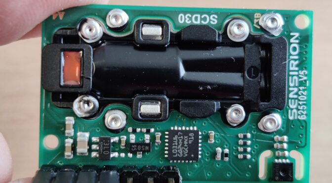
CO2 measurement with SCD30, Arduino and Matlab

Loading

This project – actually a mini project – might also be interesting for one or the other. It is the now well-known and frequently used carbon dioxide sensor SCD30 (CO2 sensor) from the manufacturer Sensirion. There are a number of projects that can be found on the internet. As part of a quick test setup, I tried to read out the data from the sensor using an Arduino Uno board in order to then display it in a plot using the Matlab software. The data transfer takes place via the serial interface or via the serial protocol of the USB-UART.

To connect the SCD30 to the Arduino, you need the power supply and the I²C data bus – so in total just four wires. This means that the minimum configuration is fulfilled and the data can be read out.

The sensor itself works on the principle of NDIR technology. (NDIR = non-dispersive-infrared). That means the sensor is a small spectrometer. The medium to be examined is fed into a sample chamber. The sample chamber is illuminated by an infrared source and the IR light shines through the medium and a very narrow-band wavelength filter and then hits the IR detector. The wavelength of the filter is designed in such a way that precisely those wavelengths are let through that are absorbed by the molecules of the medium (gas). Depending on the number of molecules or the density of the gas, fewer light beams are recognized by the detector. A second measuring chamber, which is filled with a reference gas, serves as a reference. A controller on the sensor evaluates this information and forwards it in the form of ppm via the I²C (or switchable MOD-Bus) interface. There is also a temperature and humidity sensor on the board, the data of which can also be read out via the bus. The preset I²C address of the SCD30 is 0x61. The exact information on the data protocol can be found in the documentation from Sensirion.

Ideally, as almost always, there is already a ready-made library suitable for students for the various microcontrollers. So you don’t have to worry anymore and can read out the data from the connected sensor directly. The example programs can be found under the examples of the libraries.

electrical specifications

The Arduino with 3.3V or 5V can be used for the supply voltage of the sensor. However, caution is advised when using the I²C bus: Here the input high level is set at 1.75-3.0V and the output high level with a maximum of 2.4V. But on an Arduino the levels are 5V !! So a level shifter has to be built in here – or at least, suitable resistors for a quick test.

The program code listed here essentially comes from the example of the library by Nathan Seidle from SparkFun Electronics:

 1
 2
 3
 4
 5
 6
 7
 8
 9
10
11
12
13
14
15
16
17
18
19
20
21
22
23
24
25
26
27
28
29
30
31
32
33
34
35
36
37
38
39
40
/*
By: Nathan Seidle SparkFun Electronics  
Library: http://librarymanager/All#SparkFun_SCD30  
*/

#include <Wire.h>
#include "SparkFun_SCD30_Arduino_Library.h" 
SCD30 airSensor;

void setup()  
{
  Wire.begin();
  Serial.begin(9600);
  //Serial.println("SCD30 Example");
  airSensor.begin(); //This will cause readings to occur every two seconds
}

void loop()  
{
  if (airSensor.dataAvailable())
  {
   // Serial.print("co2(ppm):");
   
    Serial.print(airSensor.getCO2());

    //Serial.print(" temp(C):");
    Serial.print(",");
    Serial.print(airSensor.getTemperature(), 1);

   // Serial.print(" humidity(%):");
    Serial.print(",");
    Serial.print(airSensor.getHumidity(), 1);

    Serial.println();
  }
  else
    //Serial.println("No data");

  delay(500);
}


With these lines of code in the Arduino Uno and the correct wiring (SDA -> to Arduino A4 and SCL -> to Arduino A5 via a suitable level converter) you can continue with Matlab. The Arduino should now output the following lines in a serial terminal: (example)

473,28.5,12.9
473,28.5,13.0
470,28.5,13.1
469,28.5,12.9
466,28.5,12.9
465,28.5,12.7
465,28.5,12.5
463,28.6,12.6
461,28.6,12.5
463,28.5,12.4 … und so weiter

This now has to be read into Matlab and recorded over a definable period and at the same time displayed in a plot. The matlab script here makes it possible … (pn if someone needs it)

The result is a plot that shows the course of CO2 in the room (in this case on my office desk).


Data Node with Arduino

Loading

Unfortunately, the intervals in which I find some time to write a new post for the blog have not gotten shorter. But post a post per month, I think … 🙂

This time it’s not a retro craft project from the local Gefielden or a restoration of an old device, but again something about Arduino. The idea – to build a sensor that, as always, transforms a physical quantity into an electrical signal. This is nothing special and what kind of sensor it will be, I will not describe for the time being. But there should not be a sensor board, but many. And these sensor boards short “sensors” are to be networked together in a two-dimensional matrix. You can imagine it as a chessboard, with each of the chessboard panels representing a sensor. This network of sensors – ie sensor nodes – should then be connected via a transfer point to a computer and output the sensor data of the respective field. It should then also be possible to remove individual fields from the network without the remaining network losing its function.

The whole system should be as simple and cheap as possible. And so a system concept was quickly developed in which the nodes communicate via the I²C bus and send their data to a master. The following diagram is intended to illustrate this.

This concept, I thought, is easiest to implement with an ATmega microcontroller. The has enough IO’s, an I²C bus and UART onboard, as well as analog inputs and requires little component peripherals to bring it to life in its own layout. And there is nothing faster to do such a test setup of such a node network than to use the well-known Arduino development boards. I have chosen the cheapest version for a test setup -> the Chinanachbau of the ArduinoUno (Joy-IT UNO) with the Atmga328 in the capped DIL housing.

Joy-It Uno Boards

The picture shows ten of these microcontroller boards. Of these, one should be used as a bus master and nine as slaves. Of course, each of these slaves has a unique bus address, which only occurs once in the system. In the test setup, this bus address is permanently assigned via the program code, since anyway each Arduino must be connected to the computer in order to carry out the program upload. Of course, that should look different later. Because the Arduino is on the Atmega328 chip, its quartz and the few resistors reduced on the sensor board with gelayoutet. The chip should then be programmed via the ISP pins. Of course, as many boards do not always customize the program code and they all have the same Flash file, I want to set the sensor address with a 7-bit DIP switch. A 4021 Cmos Static Shift Register is supposed to read the bits after the controller is powered on and push them serially into the controller. The resulting value is then available as a bus address in a variable.

Each of these slaves with their individual bus address is now queried in sequence by the master node, which state it has and whether it should switch an output or not. That is, the node has only one DO (digital output) with which it can, for example, turn an LED off and on and interrogate one or more DIs (digital input) which polls a state, for example a simple switch. These functions are stored in 2 bits of a byte. Another byte is used to transfer the bus address. So two bytes are sent over the bus. The picture below shows the test setup with the “UNO boards”

All Arduinos are connected to I²C data bus and power supply

The process is as follows:

MASTER:
The master node sends a request after the series to all slave addresses and a switch command (which comes from all nodes of a TEST push button input on the master) for the LED output of the node and sees if a response comes back or not. If no answer comes, the node is not in the network or is defective. If there is an answer, this consists of the address of the node and its status byte. This information is transmitted via an RS232 terminal to the computer connected to the master. Thus, for example, the switching status of each individual node can be displayed on the screen via a visualization using (NI LabView, or Matlab or similar). By adapting the master program, it is also possible to switch the LED outputs of the slaves via the computer.

SLAVE:
When the master node requests data from the slave, the slave sends back two bytes. Where byte0 again is the slave ID (ie bus address) and byte1 is the data. Byte1 actually consists of only two bits encoded as follows (in decimal representation):
 0 = LED off| Sensor not triggered
 1 = LED on | Sensor not triggered
 2 = LED off | Sensor triggered
 3 = LED on | Sensor triggered

The program code as an example:

 1
 2
 3
 4
 5
 6
 7
 8
 9
10
11
12
13
14
15
16
17
18
19
20
21
22
23
24
25
26
27
28
29
30
31
32
33
34
35
36
37
38
39
40
41
42
43
44
45
46
47
48
49
50
51
52
53
54
55
56
57
58
59
60
61
62
63
64
65
66
67
68
69
70
71
72
73
74
75
76
77
78
// I2C Slave Code
// 16.05.2018 
// ver 1.3
#include <Wire.h>
#define ADDRESS 2     // adresse des slave knotens
#define PAYLOAD_SIZE 2 // anzahl der bytes  die vom masterknoten zu erwarten sind
int LED=12;            // indicator led an pin D12
int SENSOR = 8;        // sensor input an pin D8
bool actionState=0;      // sensor zustand
int busstatus;  // statusvariable 
                       // 0 = LED aus | sensor nicht belegt
                       // 1 = LED ein | sensor nicht belegt
                       // 2 = LED aus | sensor belegt
                       // 3 = LED ein | sensor belegt
 
bool sensled=0;          // sensor LED
byte nodePayload[PAYLOAD_SIZE];

void setup()
{
  pinMode(LED, OUTPUT);         //sensorLED
  pinMode(SENSOR, INPUT);       //Sensor 
  Wire.begin(ADDRESS);          // Activate I2C network
  Wire.onReceive(receiveEvent);
  Wire.onRequest(requestEvent); // auf master anforderung warten
                      //  // debug interface
                      //  Serial.begin(9600); 
}

// *********************************mainloop****************************************************
void loop()
{ 
  delay(5);
  
   if(sensled){digitalWrite(LED, HIGH);}
         else{digitalWrite(LED, LOW);}

  actionState = digitalRead(SENSOR);  //Sensoreingang abfragen        
   if((actionState==1)&&(sensled==1)) {busstatus=3;}
   else if ((actionState==0)&&(sensled==1)) {busstatus=1;}
   else if ((actionState==1)&&(sensled==0)) {busstatus=2;}
   else if ((actionState==0)&&(sensled==0)) {busstatus=0;}

                      //  Serial.println("######################");
                      //  Serial.print("busstatus neu setzen ");
                      //  Serial.println(busstatus);
                      //  Serial.print("sensled LED            ");
                      //  Serial.println(sensled);
                      //  Serial.print("actionState           ");
                      //  Serial.println(actionState);
                      //  Serial.println("######################");
  nodePayload[0] = ADDRESS;                  // Adresse in byte0 zurücksenden.  
  nodePayload[1] = busstatus;                //byte 1 ist die statusinfo der LED
}


// *********************************************************************************************
void requestEvent()
{ Wire.write(nodePayload,PAYLOAD_SIZE);  
  Serial.println("bytes status schreiben");
  Serial.println(nodePayload[0]);
  Serial.println(nodePayload[1]);
  delay(5);
}

// *********************************************************************************************
void receiveEvent(int bytes)  //einen wert vom I2C lesen
      
{
  
  busstatus = Wire.read(); //If the value received was true turn the led on, otherwise turn it off  
                              //  Serial.println("status empfangen");
                              //  Serial.println(busstatus);
  if((busstatus==1)||(busstatus==3)){sensled = 1;}
                                else{sensled = 0;}
                                              
}


The bus address must still be entered individually in this slave code. In the next version, the previously described “serializer” of the parallel dip-switch variant will be implemented. The following code example is from the master node, which reads out the slaves and sends a LED pattern to the sensor slaves using the test button:


  1
  2
  3
  4
  5
  6
  7
  8
  9
 10
 11
 12
 13
 14
 15
 16
 17
 18
 19
 20
 21
 22
 23
 24
 25
 26
 27
 28
 29
 30
 31
 32
 33
 34
 35
 36
 37
 38
 39
 40
 41
 42
 43
 44
 45
 46
 47
 48
 49
 50
 51
 52
 53
 54
 55
 56
 57
 58
 59
 60
 61
 62
 63
 64
 65
 66
 67
 68
 69
 70
 71
 72
 73
 74
 75
 76
 77
 78
 79
 80
 81
 82
 83
 84
 85
 86
 87
 88
 89
 90
 91
 92
 93
 94
 95
 96
 97
 98
 99
100
101
102
103
104
105
106
107
108
109
110
111
112
113
114
115
116
117
118
119
// I2C masterknoten 
// 16.05.2018 
// ver 1.2
// changes abfrage wenn kein knoten am bus dann 255 ausgeben
#include <Wire.h>

#define busbytes 2          // wievele byte vom I2C knoten zu erwarten sind
#define maxKNOTEN  10       // anzahl der zu scannenden slaves
#define startKNOTEN 2       // startadresse der slaves
#define DELAY 5             // einfach ein delay ....

int i; int j=0;
int buttonPin = 12;
int testbut = 0; int anim = 0;
int buttonState = 0;
int DATEN[busbytes];
int adresse; int busstatus;  
byte sensorbelegt; byte ledsensoron;

                       // 0 = LED aus | Sensor nicht belegt
                       // 1 = LED ein | Sensor nicht belegt
                       // 2 = LED aus | Sensor belegt
                       // 3 = LED ein | Sensor belegt

int leddat1[] = {1,1,1,1,0,1,1,1,1}; // -
int leddat2[] = {0,0,0,0,1,0,0,0,0}; // |

void setup()
{
  Serial.begin(9600);  
  Serial.println("MASTER-KNOTEN");
  Serial.print("Maximum Slaveknoten: ");
  Serial.println(maxKNOTEN);
  Serial.print("Datengroesse in byte: ");
  Serial.println(busbytes);
  Serial.println("***********************");
  
  Wire.begin();                 // Activate I2C link
  pinMode(buttonPin, INPUT);    // test-tastereingang festlegen
}


//#####################################################################################################
void loop()
    
{
  for (int Knotenadresse = startKNOTEN;         //alle knoten scannen
           Knotenadresse <= maxKNOTEN; 
           Knotenadresse++) 

        
    //################################################################################################       
    { 
     // testbut = 0;  
     anim = 0;   
    Wire.requestFrom(Knotenadresse, busbytes);        // daten vom jeweiligen knoten anfordern
                                                 
           DATEN[0]=255; DATEN[1]=255;   // wenn kein knoten dann auf 255 setzen    
          if(Wire.available() == busbytes) {                                    // wenn knoten und daten dann
            for (i = 0; i < busbytes; i++) DATEN[i] = Wire.read();          // daten holen (zuerst busID, dann daten)
           // for (j = 0; j < busbytes; j++) Serial.println(DATEN[j]);        // daten an rs232 ausgeben   
          }            

//            Serial.println(Knotenadresse);
//            Serial.println(DATEN[0]);
//            Serial.println(DATEN[1]);
//            Serial.println(" ");
           
            adresse=DATEN[0]; 
            busstatus=DATEN[1];
           
            if(busstatus == 0)       {sensorbelegt=false;  ledsensoron=false;}
            else if (busstatus == 1) {sensorbelegt=false;  ledsensoron=true;}
            else if (busstatus == 2) {sensorbelegt=true;  ledsensoron=false;}
            else if (busstatus == 3) {sensorbelegt=true;  ledsensoron=true;}
      
         //################################################################################################
         //Testbutton Status lesen und variable testbut entsprechend setzen
       
          buttonState = digitalRead(buttonPin);               //tastereingang einlesen
          if(buttonState == HIGH){                            //wenn taster aktiv dann variable anim setzen
          anim = 1;
          //delay(5); 
          }
            
//            //debug debuginfo tasterstatus auf rs232 ausgeben
//            Serial.println("#######################");
//            Serial.print("Knoten Adresse    :");
//            Serial.println(adresse);
//            Serial.print("Busstatus         :");
//            Serial.println(busstatus);
//            
//            Serial.println("----------------");
//            Serial.print("Fliese belegt    :");
//            Serial.println(sensorbelegt);
//            Serial.print("LED Fliese       :");
//            Serial.println(ledsensoron);
//            Serial.print("#######################");
//            Serial.println(" ");
      
          //################################################################################################
          //Testbutton Status an jeweiligen knoten senden
      
          Wire.beginTransmission(Knotenadresse);           // transmit to device actual in for loop
          //anim schreiben
                    
           if (anim==0) {testbut=leddat1[j]; j++;}
                   else {testbut=leddat2[j]; j++;}
           if (j>8){j=0;}
          
          Wire.write(testbut);                             // senden des tasterstatus
          Wire.endTransmission();                          // ende gelände mit uerbertragung
       
          delay(DELAY);
          

    }
   
}


With this arrangement, it is now possible to read all Arduinos and their input or to control the LED via the bus. In the next step, a “sensor” is built, a board is laid out and the ArduinoUno reduced to its microcontroller. I’ll talk about that in one of the next posts …


Radioreceiver in retro look – The finishing

Loading

IMAG1299
The wooden case is painted

Now that the front panel is milled, it can be cleaned and the engravings are provided with black paint. After the varnish has dried in the indentations of the engraving, the supernatant paint is removed with solvent. Now the entire panel could be painted with clear lacquer.

While the paintwork on the front panel is drying, it’s time again for the wooden cabinet. The mounting holes for the boards, speakers, etc. were drilled and then the wood was embedded with a slightly darker wood stain. After drying, the wooden case also gets a clear coat.

In the next step, the operating elements (switches and rotary encoders) and the LC display are attached to the front panel. The milled webs for the speaker panel are covered with black fabric. (For the fabric had to serve a T-shirt).

IMAG1307


The painting of the housing dried about a day. Now you can start mounting the speakers and the board.

IMAG1301
Installation of the speakers


Die Platine wird mit Abstandhaltern am Gehäuseboden verschraubt.

IMAG1302
Assembly of the board


Now a suitable power supply is missing. For this purpose, a small power supply was built, which consists only of an iron core transformer with subsequent rectification, smoothing and voltage stabilization with a LM7809, ie 9V DC. For this, a small board was made (about 5x8cm) and also built into the housing with spacers.

IMAG1328
Power supply 240V AC to 9V DC at max. 350mA


Now that everything is assembled, the amplifier metrics and levels are again set and optimized with signal generator and oscilloscope.

IMAG1332
Adjustments


The finished radio receiver now looks like this from the front …

IMAG1308
Radio from the front


und die Geräterückseite ist im nächsten Bild dargestellt:

IMAG1333
back

In the short video, the radio can be seen in operation:

Radioreceiver in a retro look – Update: The case

Loading

IMG-20150130-WA0000-2 It’s time! The first picture of the absolutely real wooden housing for radio electronics is here. A beautifully crafted housing made of glued elements. This work comes from Gebhard’s hands, a master carpenter from the Upper Carinthian region;)

IMAG1272
Housing with holes for the speakers

Jetzt kann das Nostalgie-Radioprojekt wieder einen Riesenschritt nach vorne machen.

frontpanel
This will be the aluminum front panel

The case is on our table. First, the holes for the speakers were drilled. Later these should be covered by a milled aluminum panel. So the next step is to construct the milling data for the front panel. Here again the layout tool “Eagle” is used. The data can simply be exported as a “.dxf” file and imported into the circuit board plotter software.


UPDATE:

Barely a few minutes, I went to the circuit board plotter, imported the production data, clamped the “two-cutter cutter”, of course, the aluminum blank and off we went.

The speed for the 1mm cutter I have chosen with 60000 rpm and set the feed rate to 1.5mm / s in both axes. Cooled and lubricated was the way with alcohol.

A not negligible amount of work is, by the way, the cleaning of the plant after the work done … 🙂

IMAG1281


Radio in retro-look – KnowHow for the apprentice – Part 2

Loading

… to realize the volume control via the microcontroller, a “digital potentiometer” X9C102 was simply used. It is controlled directly by the controller with a “direction input Up / Down” and a “count input”. Internally, this IC consists of 100 resistors connected in series whose “tap” is determined by counting input. So a simple matter to control the signal level of the preamplifier in 100 steps ….


Continued from Radio Part 1
The controller should now be operated via a push / turn wheel (rotary encoder with push button). In order to be able to evaluate the direction of rotation of rotary encoders, a second pulse output is required. The two pulse outputs must be shifted in their sequence depending on the direction of rotation (phase shift). In order to convert the pulse sequence into a direction signal and a clock signal, we have set up a small decoder logic using a JK flip-flop and a Schmitt trigger / inverter …

Turnwheeldecoder

The outputs of the decoder logic are now passed directly to three microcontroller inputs. Thus, now a suitable program can be created, which provides a simple menu-driven user interface. The parameters are displayed on a two-line LC display. The outputs of the controller, in turn, control the “digital potentiometers” for the volume setting and, of course, the I²C bus, which sends the commands to the FM module. An additional output allows the switching of a relay, with which, for example, the audio input from the amplifier can be switched between the FM module and an external signal source. The LC display is connected to the controller in 4-bit mode and the backlight of the display is also switched by the controller.

 
PCB fresh from production

After all these functionalities had been defined, we were going to transfer this information to the Layout Tool or the schematic.
Finally, a layout was drawn and made. Subsequently, we could start with the assembly of the board and then carry out the first commissioning. After the adjustment of the amplifier quiescent currents, the development of the Arduino code began. Here, the work is extremely facilitated, since there are many finished libraries here, which can be used directly for its purposes. For example, the only challenge with getting an LC display up and running is to connect the few wires to the uC (microcontroller) and pinpoint the pins in the code. Everything else is done by the library. With this simplification, the functions are then implemented quickly and the first test run can begin.

ready assembled PCB

As a result, the software will be even better – perhaps saving multiple stations, and so on. But the next step will be to build the board into an enclosure modeled on the old radio tube radio receivers. It should be made of solid wood. The operating and display elements are to be installed in an aluminum plate placed on the front of the housing … (Another post on this blog will follow.)

The first functional test can be seen in the video below …


Radio in retro-look – KnowHow for the apprentice – Part 1

Loading

THE IDEA FOR THE PROJECT
A project idea that came to my mind as an ideal apprentice project is to plan and build a radio receiver. With this project, our apprentice should apply the acquired skills in a practical way and set up an FM radio receiver according to the components to be used.
This was done gradually. I came up with the concept in the following parts:

THE AMPLIFIER
First, a simple class A audio amplifier should be built. The apprentice should build the amplifier according to the circuit on the breadboard, metrologically examine and understand above all. In the next step, the Class A amplifier became a Class-AB amplifier. Again, the task of the apprentice was to understand the operation and optimize the breadboard function pattern so that a (not metrologically) at least reasonably “good” acoustic result was achieved.

First functional pattern of the “power output stage”

When this succeeded after some time, he got the task to transfer the determined circuit into a layout tool and expand it to a second channel, while also creating a power supply concept. The power supply should not only supply the amplifier output stage, but also for other components (such as microcontrollers, USB interfaces and what ever came to mind) a + 5V and + 3.3V DC supply available.
After many layout designs, he then presented me with a layout in which the components were symmetrical and technically reasonable (Trimmpotis should be accessible …) were arranged. So he was allowed to make the layout as a functional sample. (etch the board, populate it and try to get it all working).

The learning effect was gigantic: D, because in the implementation of theoretical circuits to a simple breadboard construction and then to the “printed” circuit on the print, there is a lot of sources of error. And they also want to be found and corrected. Our trainee was able to practice patience and precise work.
But in the end, the 440Hz sinewave of the frequency synthesizer sounded from both connected speakers …

Now it was time to think about the signal source, the actual receiver.

THE FM RECEIVER

FM-Receivermodul

In a Chinese online shipping I discovered an FM receiver module with a very compact design (a print with about 12x12mm) on which a complete receiver is integrated. The module is called TEA5767 and uses the eponymous Philips FM receiver chip.
The connections to the module consist of power supply, audio L and R outputs, as well as an I²C bus to control or set the reception frequencies and an antenna and Muteeingang. So ideal to realize a signal source for our amplifier. But that raised further questions.
How should one generate the control signals for the I²C bus, how should the tuning of the transmitters be done, how should the device be operated by the user at all? For all these questions, there is a simple answer: Take a microcontroller. And as the apprentice likes experimenting with the Arduino UNO board, I decided to use an Atmega328, the Arduino UNO controller.

THE HEART OF THE RADIO – THE CONTROLLER

The microcontroller should therefore take over the complete management of the radio, thus fulfilling the following functions:

  • set the stations (generate I²C commands and send them to the radio module)
  • save the tuned stations (in the internal EEPROM of the controller)
  • show all information on a LC display
    take over the volume control
  • generate operation by means of a push / turn wheel (incremental encoder with touch function should take over the entire operation of the radio)
 Folie1
blockschematic

So we had to extend the circuit by a few components. The audio output of the FM module had to be pre-amplified. This was done by a small AudioOPAmp. To realize the volume control via the microcontroller, simply a “digital potentiometer” X9C102 was used. It is controlled directly by the controller with a “direction input Up / Down” and a “count input”. Internally, this IC consists of 100 resistors connected in series, whose “tap” is determined by counting input. So a simple matter to control the signal level of the preamplifier in 100 steps.

continue in the next part

Geiger counter and radioactivity

Loading

One project that had long been of interest to me was the detection of radioactive radiation. After the horrible powerplant accidents in Japan, this idea was recalled. I could still vaguely remember owning an unused counter tube somewhere in my old workshop cellar. – After some search it turned up :). Thanks to the Internet and the search engines, a data sheet was also found quickly. The counter tube is a ZP1400. A self-extinguishing Geiger-Müller counter tube with mica window. The tube is according to data sheet with neon and argon filled as quenching gas. The operating voltage is 400 to 600V. The capacity between anode and cathode is about 2pF. With these and other information from the data sheet i now can tinker a circuit to take the tube in operation. I have used this small project to introduce our apprentice to the board layout at the same time and to get acquainted with the creation of small programs on the Arduino Uno microcontroller board. In this post I introduce only the “old-fashioned” circuit, where only the impact of ionizing radiation is made audible to the count wire. (the typical crackling). This circuit then provided the basis for the apprentice to realize the count of the pulses with the microcontroller and to visualize it on a two-line LCD.
Wiring diagram with high voltage supply and pulse amplifier

Using the well-known layout software Eagle, I have drawn a circuit in which the high voltage is again generated by a switched transformer and subsequent Greinacher cascade. The control takes over this time no 555er, but simply a feedback Schmitt trigger. The time base is set via the coupling resistor and the capacitor. Thus, the high voltage is available for the counter tube. In order to be able to count the impulses, two factors are ensured. The impulse must not exceed a certain height. (Otherwise the following electronics may die) and the pulses should be audible (boosted). So the peaks are limited with a zener diode circuit and put into a “nice” shape with Schmitt triggers and then led to an op amp. At the output of the op-amp then hangs first a small speaker …

Arrangement of components on the PCB

After the circuit board was etched and assembled, it was time to test. But with what? I needed some weak source. I held all sorts of items in front of the counter, but it did not change much. There was a cracking sound from the speaker four to eight times a minute. So I started researching the net again. And came across the term “radium color”. This is the self-luminous color with which the dials of old watches were painted, in order to be able to read the time even in the dark. This information gave me an idea. From my grandfather i inherited once an altimeter of a WW1 aircraft (manufacturer LUFFT) whose dial might have been painted with that kind of color. So get out of the showcase and held in front of the counter tube … The result can be seen in the video.