Motorized TV ceiling mount control via Home Assistant

Loading

Since I’ve been working on home automation, I’ve naturally wanted to optimize and simplify as much as possible and adapt and implement it in line with the new buzzwords “green electronics”, “sustainability”, “energy-saving” … and so on. For example, my appliances switch off when they are not used or ignored, stand-by energy consumption is largely avoided and IOT technology also prevents human forgetfulness (leaving windows open in winter or forgetting to switch lights off). As readers of the blog already know, I use systems such as HomeMatic, NodeRed and, for some time now, Homeassistant with ESPHome, Zigbee2Mqtt etc. Of course, the aim is also to keep all systems cloud-free. I don’t want the data to take a detour via some server in the Far East to switch a light on and off in my home. So, if possible, everything should take place within my own network and not “phone” to the outside and also work if I cut the data line.

For a long time now, various suppliers have been offering an extremely practical device for comfort in the parents’ quiet room. I’m talking about a space-saving way of accommodating the flicker box (nowadays also known as a flat-screen TV) in the room. I’m just mentioning terms like:

Speaka Professional TV ceiling mount electric motorized (1439178) or MyWall HL46ML … etc. Some of these devices can be controlled with a wireless remote control, others via the Tuya CloudApp. You can bypass the Tuya app via the Tuya IOT development environment and bring these devices into your home assistant via the “TuyaLocal” integration – it works – but it’s more of a “ONLY” solution. In my opinion, the ideal solution is to integrate these devices into the ESPHome system. Using the Speaka Professional TV ceiling mount as an example, I will show you how it can be integrated into the ESPHome network and thus into the Home Assistant with a small extension. This version of the SpeaKa part has no Internet connection and is only controlled via a wireless remote control.

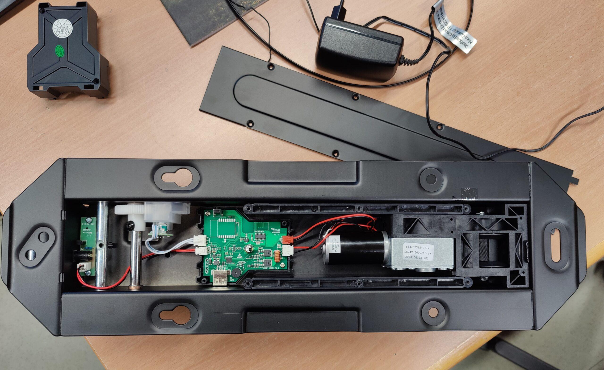
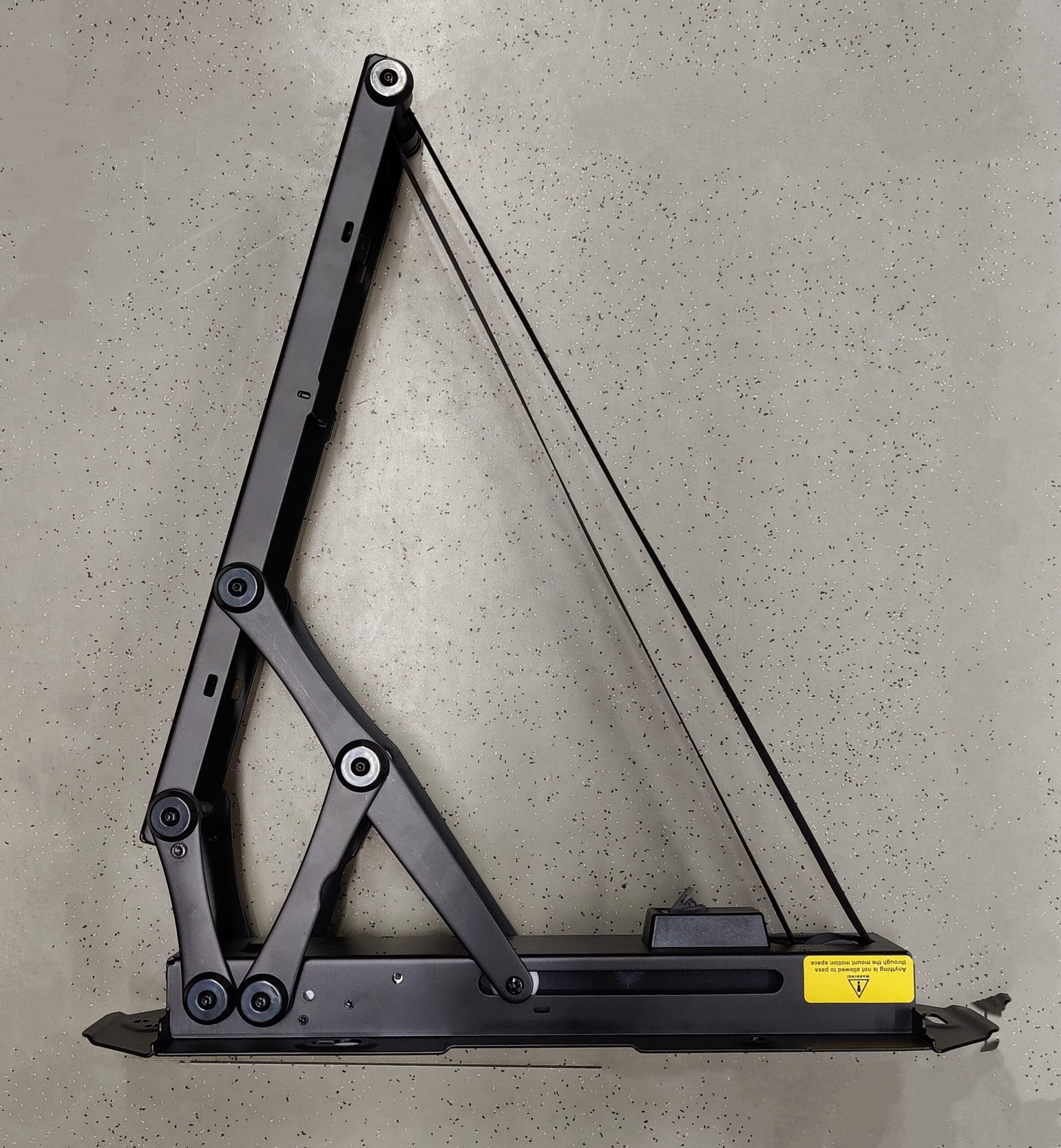
TV ceiling mount with open cover

With a little reverse engineering, we (my colleague Werner and myself) analyzed the existing appliance factory. The system is structured something like this:

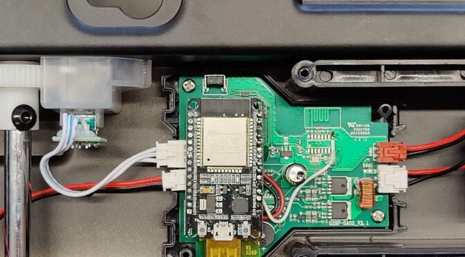
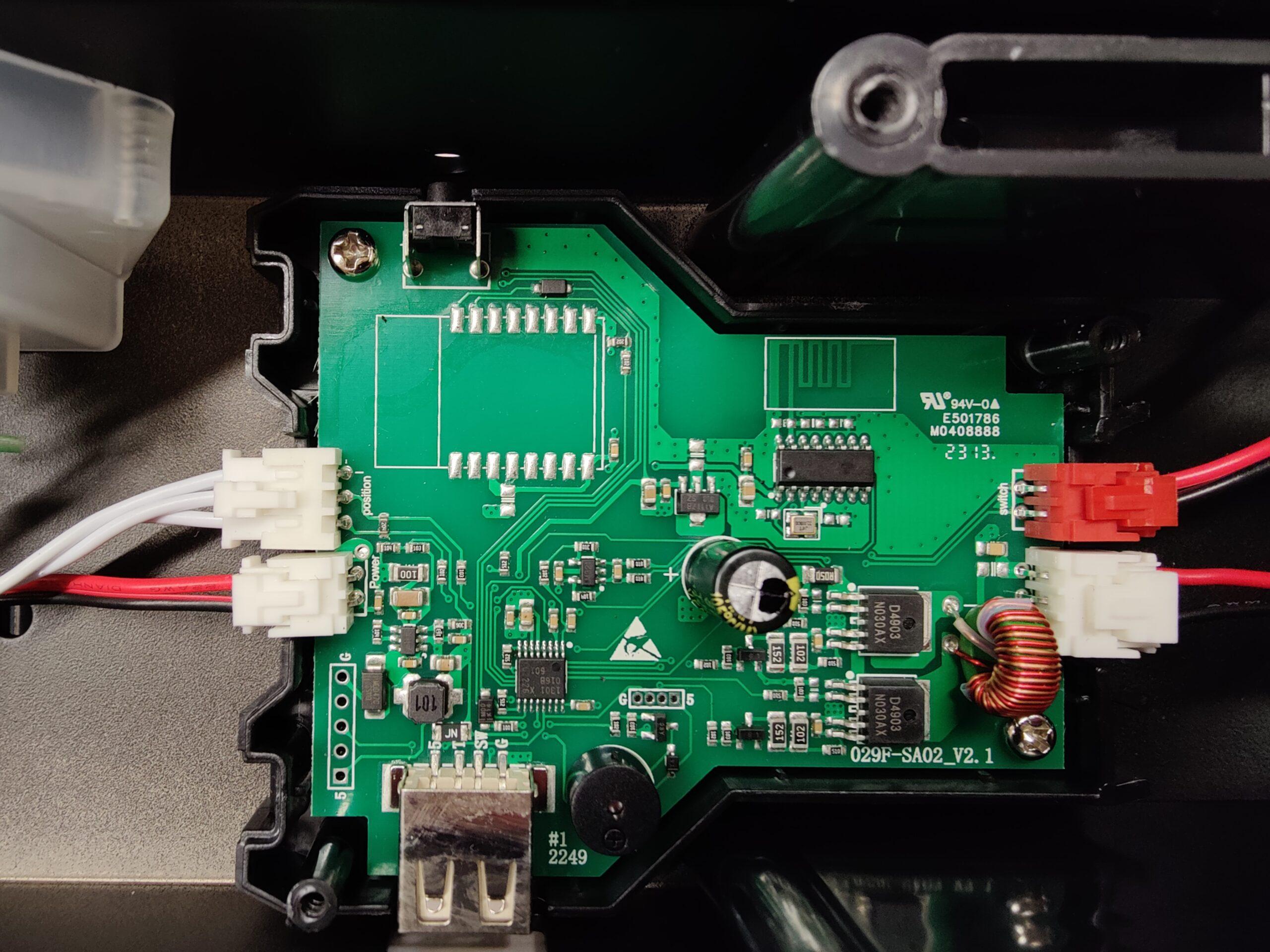
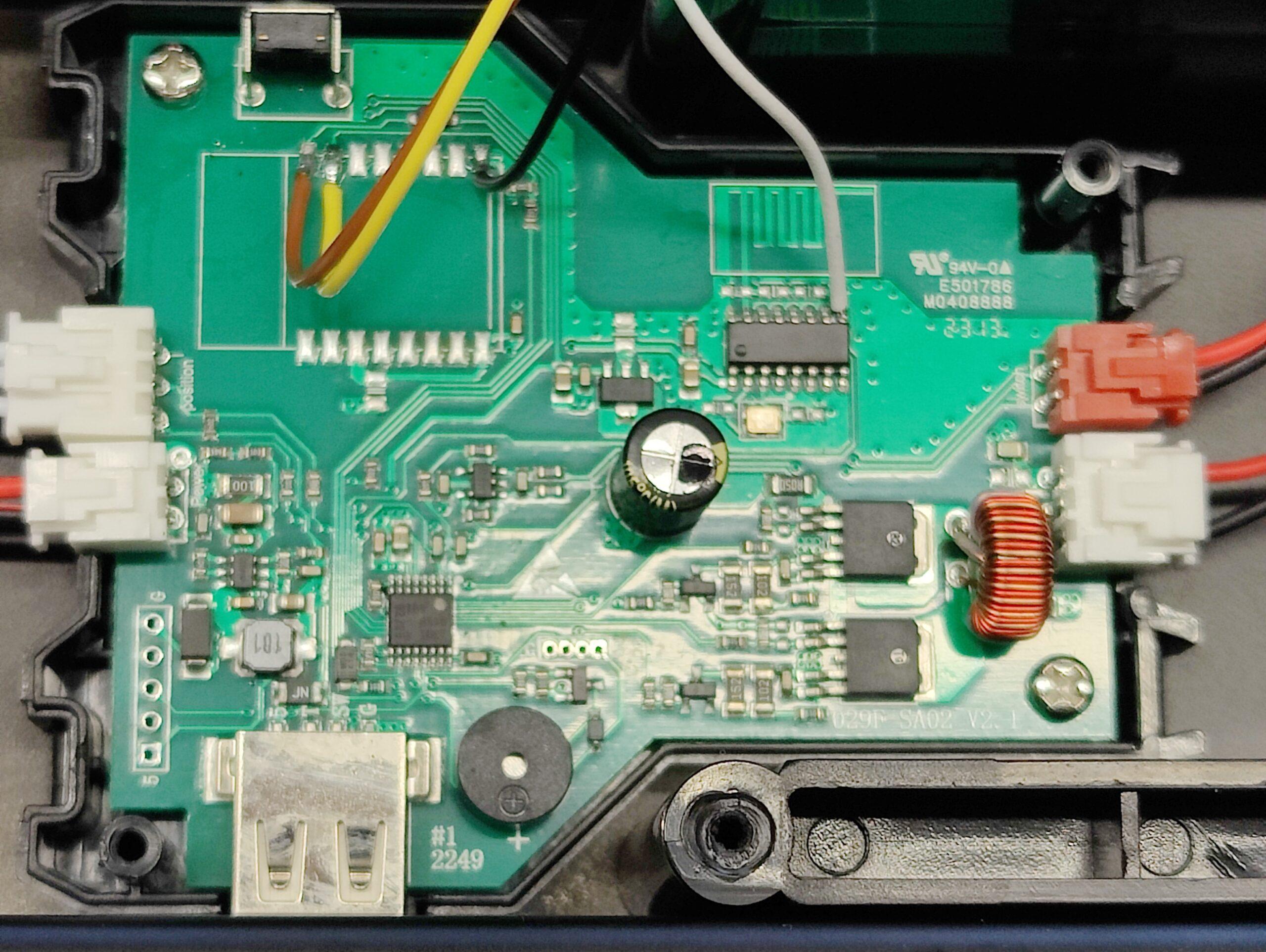
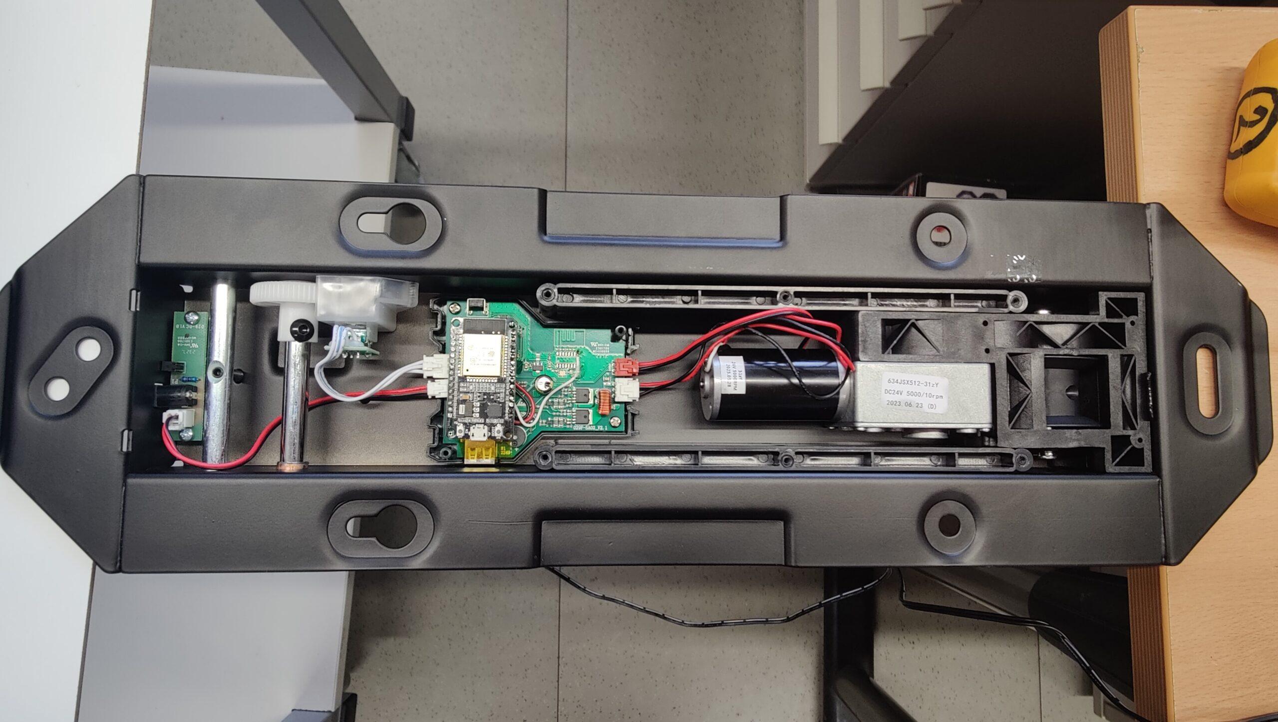
Circuit board in the ceiling bracket
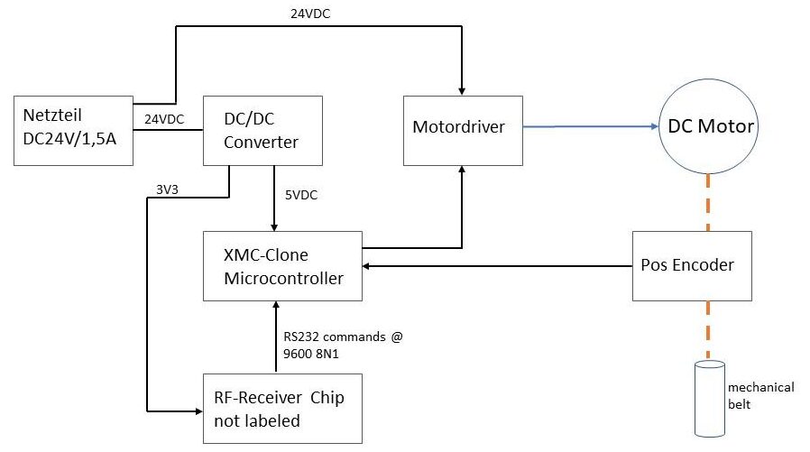
 

Systemdiagramm

The system diagram above shows how the circuit board is constructed. The power supply comes from a plug-in power supply with DC 24V output at 1.5A. On the board you can still see an unpopulated area whose solder pads are wired with +3V3, GND and RX, TX lines suitable for an ESP8266. A USB socket can also be seen. These two interfaces are not included in the diagram. We examined the RX/TX lines that are routed from the unpopulated solder pads (ESP8266) to the microcontroller (1301 X 016B). However, no signals could be measured here. (Presumably the interface is not activated in the flashed program version).

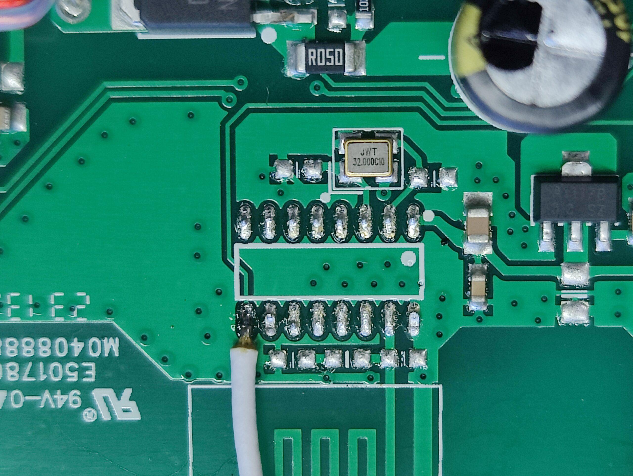
“Debug” wires on the RX/TX and on the RF chip

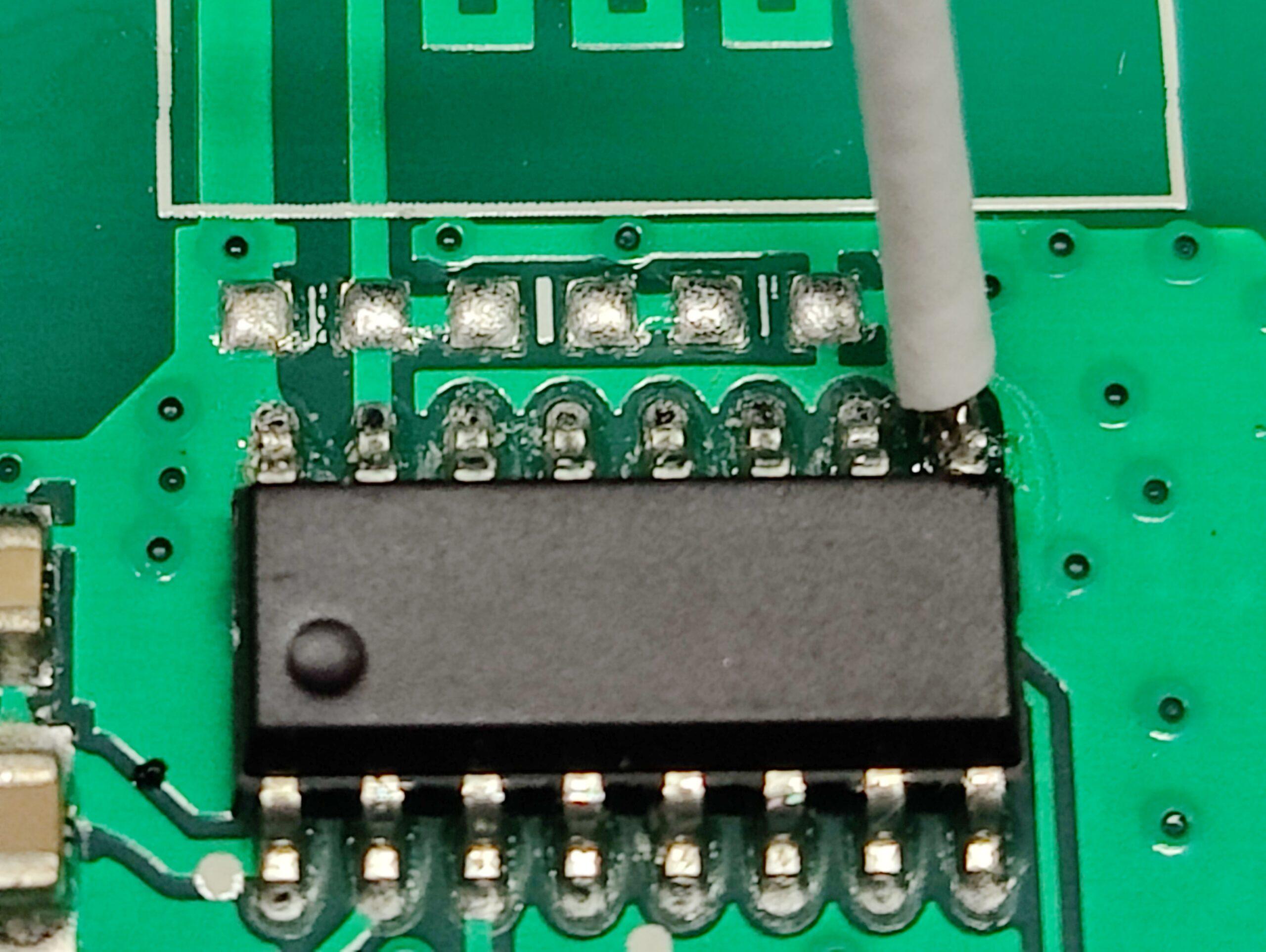
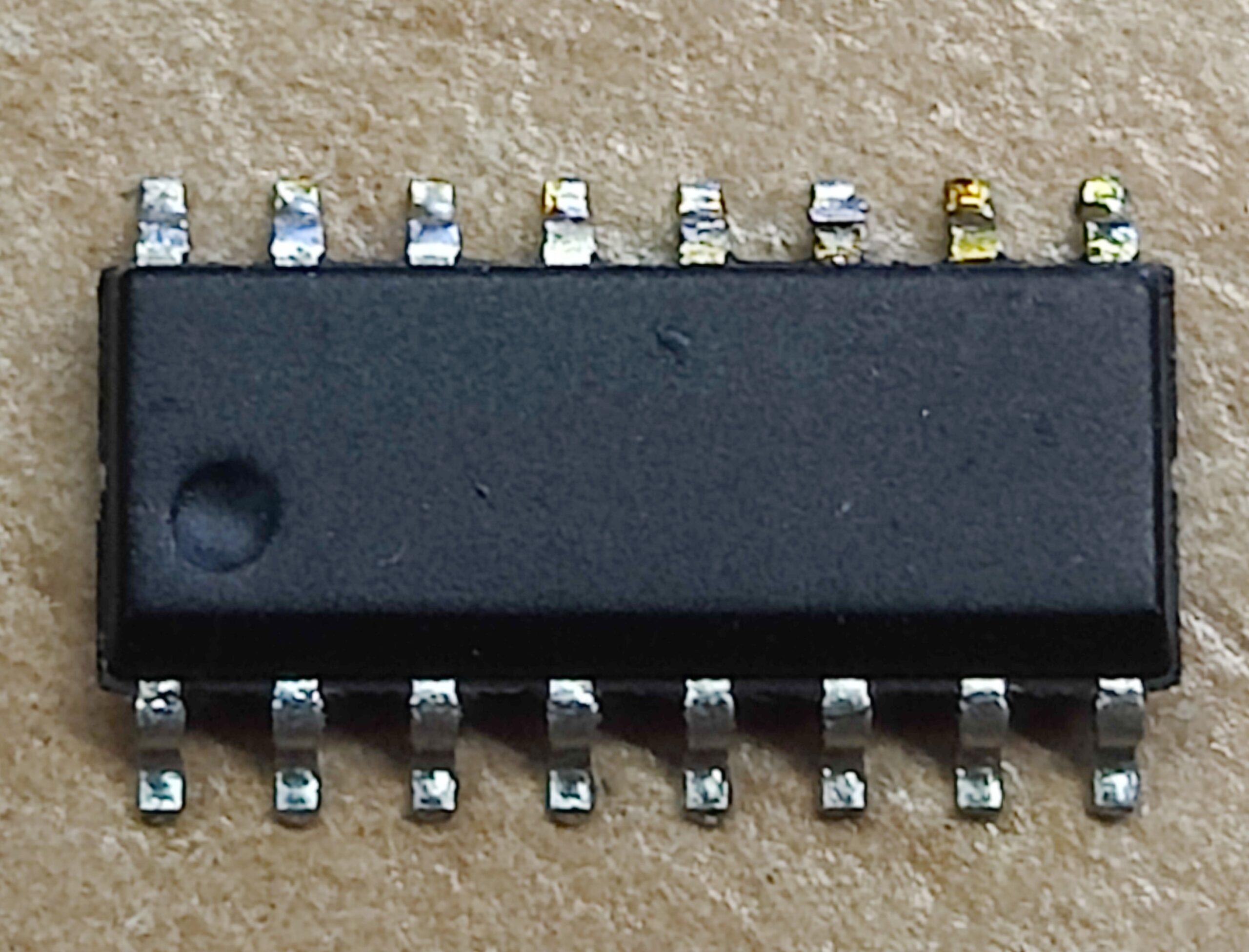
So this does not take us any further. In the next step, we looked at where the control signals of the radio remote control come from and how they are subsequently implemented. The RF receiver chip has 16 pins and unfortunately no labeling. Or has it been removed? The supply voltage of the RF chip is connected to pin 1 and pin 16, pin 2 and pin 3 are connected to a crystal and a line is routed from pin 9 to the microcontroller. So this must be the data output. Using the “PulseView” software from Sigrok and a Far East logic analyzer, we sniffed this output. And lo and behold, data packets with a duration of 10.3ms were revealed here. The PulseView software was able to recognize the protocol as an RS232 protocol after a few attempts with different analyzed data rates. It was then easy to log the received and decoded control commands to the microcontroller.

RF chip with connected “sniffer” cable

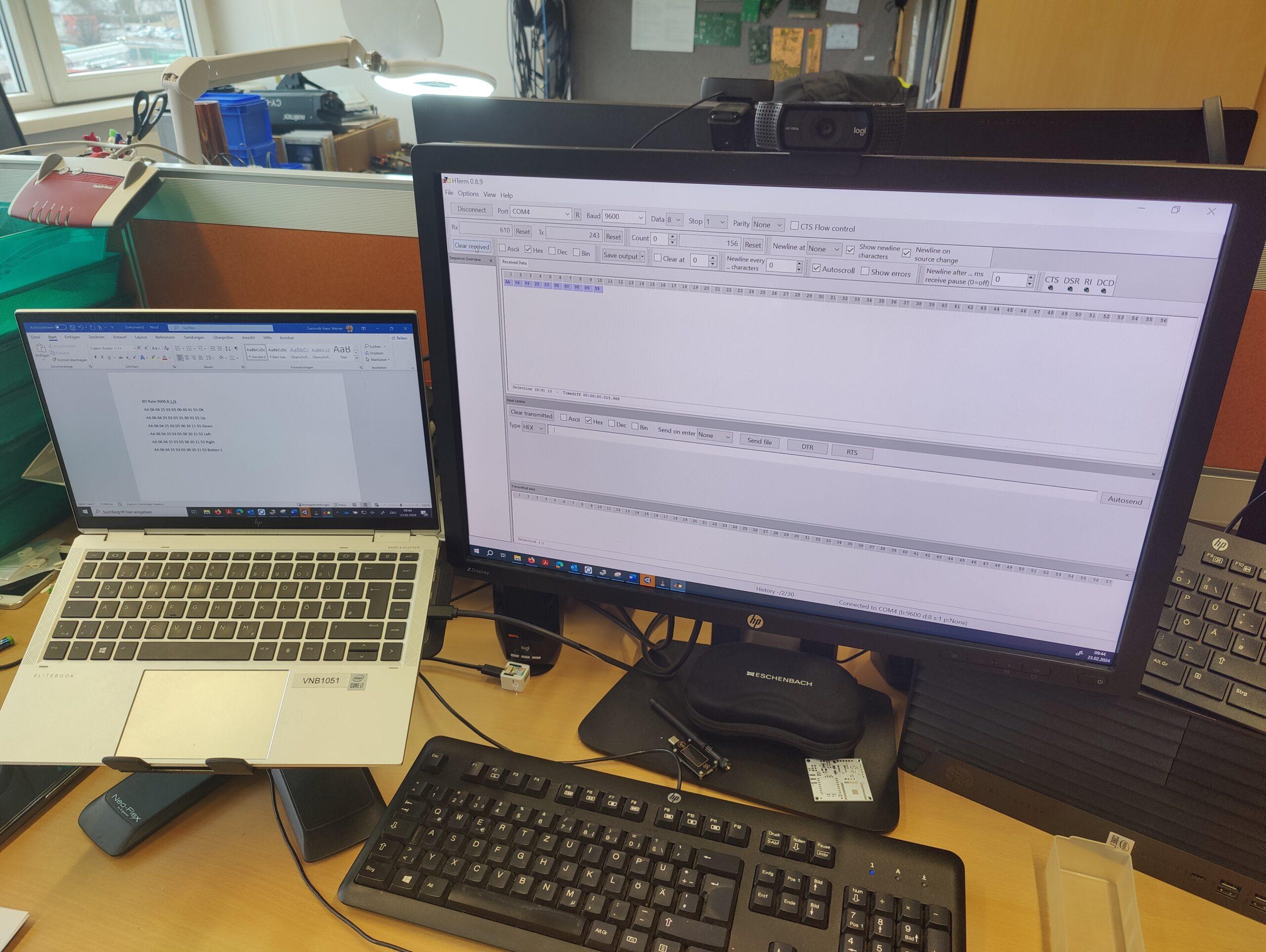
The baud rate of the RS232 port on the RF chip output is 9600 at 8N1. 10 bytes are received in HEX for each command sent. Here is the list of commands: (missing bytes follow…maybe sometime)

Befehl Byte0 Byte1 Byte2 Byte3 Byte4 Byte5 Byte6 Byte7 Byte8 Byte9
UP 0xAA 0x06 0x04 0x25 0x03 0xD5 0x01 0x00 0x02 0x55
DOWN 0xAA 0x06 0x04 0x25 0x03 0xD5 0x00 0x10 0x11 0x55
LEFT 0xAA 0x06 0x04 0x25 0x03 0xD5 0x55
RIGHT 0xAA 0x06 0x04 0x25 0x03 0xD5 0x55
BUTTON1 0xAA 0x06 0x04 0x25 0x03 0xD5 0x55
BUTTON2 0xAA 0x06 0x04 0x25 0x03 0xD5 0x00 0x08 0x09 0x55
MEM1 0xAA 0x06 0x04 0x25 0x03 0xD5 0x55
MEM2 0xAA 0x06 0x04 0x25 0x03 0xD5 0x55
OK 0xAA 0x06 0x04 0x25 0x03 0xD5 0x00 0x40 0x41 0x55
SET xx xx xx xx xx xx xx xx xx xx

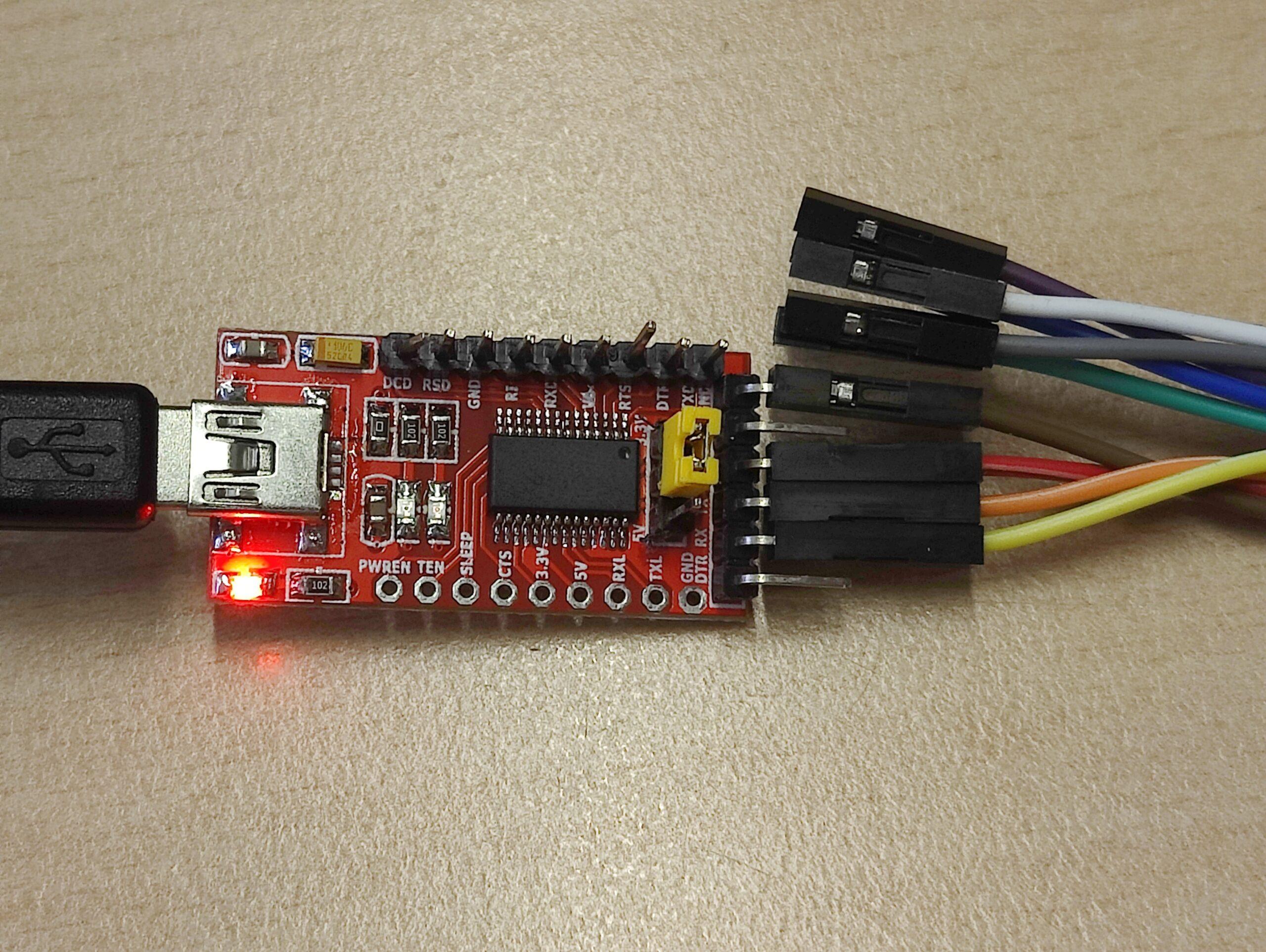
Once the data protocol had been found using the logic analyzer, we tried to send the data to the microcontroller using a terminal program and a USB to TTL232 converter. The RF chip was removed for this purpose. It pulled the level to VCC in the idle state and prevented parallel operation of the “RS232 transmitter”.

RF-Chip removed
Board without chip with debug line


USB UART for sending commands

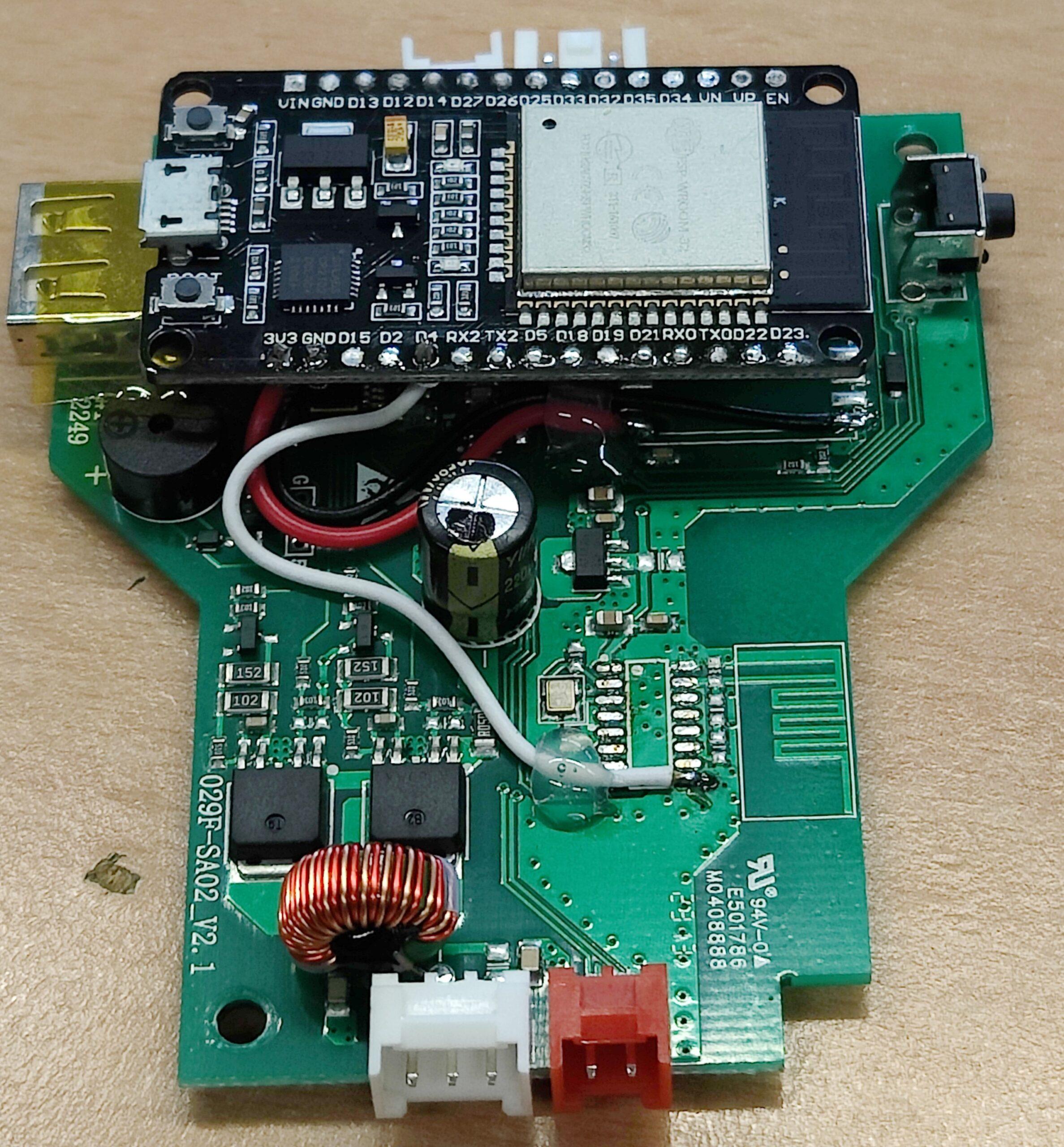
The control commands from the table above could be successfully sent via the terminal program. Now only an ESP32 board had to take over this task. An ESP32 NodeMCU board from the pool was equipped with a basic ESPHome image and integrated into the Homeassistant network. The ESPHome node now only had to be taught to send the byte sequence via the TX pin of the ESP32 when the corresponding trigger was activated in the Homeassistant. To do this, the ESP32 board was attached to the PCB and the VCC3V3, GND and TX lines were soldered to PIN9 of the former RF chip.

ESP32 on the board of the Speaka ceiling bracket


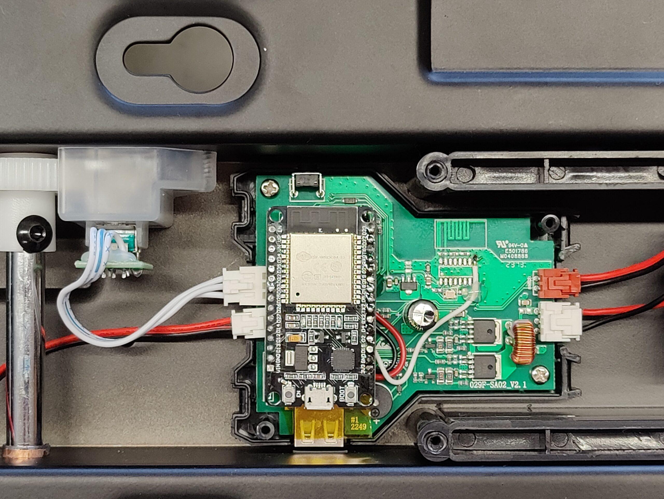
Re-installed in the ceiling bracket

The following esphome script must now be added to the ESPHome web environment.

 esphome:  
  name: tvhalterung  
  friendly_name: TVHalterung  
   
 esp32:  
  board: esp32dev  
  framework:  
   type: arduino  
   
 # Enable logging  
 logger:  
   
 # Enable Home Assistant API  
 api:  
  encryption:  
   key: "hier dein key beim Anlegen des device"  
   
 ota:  
  password: "hier dein ota password"  
   
 wifi:  
  ssid: !secret wifi_ssid  
  password: !secret wifi_password  
   
  # Enable fallback hotspot (captive portal) in case wifi connection fails  
  ap:  
   ssid: "Tvhalterung Fallback Hotspot"  
   password: "hier wieder deins"  
   
 captive_portal:  
   
 uart:  
  tx_pin: 4  
  rx_pin: 5  
  baud_rate: 9600  
   
 # Example button configuration  
 button:  
  - platform: template  
   name: TV Halterung UP  
   id: tv_up  
   icon: "mdi:arrow-up-bold-outline"  
   on_press:  
    - logger.log: "Button pressed TV Up"  
    - uart.write: [0xAA,0x06,0x04,0x25,0x03,0xD5,0x01,0x00,0x02,0x55]  
    
  - platform: template  
   name: TV Halterung OK  
   id: tv_ok  
   icon: "mdi:stop-circle-outline"  
   on_press:  
    - logger.log: "Button pressed TV OK"  
    - uart.write: [0xAA,0x06,0x04,0x25,0x03,0xD5,0x00,0x40,0x41,0x55]  
   
  - platform: template  
   name: TV Halterung DOWN  
   id: tv_down  
   icon: "mdi:arrow-down-bold-outline"  
   on_press:  
    - logger.log: "Button pressed TV Down"  
    - uart.write: [0xAA,0x06,0x04,0x25,0x03,0xD5,0x00,0x10,0x11,0x55]  
   
  - platform: template  
   name: TV Halterung Button1  
   id: tv_button1  
   icon: "mdi:numeric-1-circle-outline"  
   on_press:  
    - logger.log: "Button pressed TV Button1"  
    - uart.write: [0xAA,0x06,0x04,0x25,0x03,0xD5,0x00,0x20,0x21,0x55]  
   
  - platform: template  
   name: TV Halterung Button2  
   id: tv_button2  
   icon: "mdi:numeric-2-circle-outline"  
   on_press:  
    - logger.log: "Button pressed TV Button2"  
    - uart.write: [0xAA,0x06,0x04,0x25,0x03,0xD5,0x00,0x08,0x09,0x55]  
    
  - platform: template  
   name: TV Halterung Left  
   id: tv_left  
   icon: "mdi:arrow-left-bold-outline"  
   on_press:  
    - logger.log: "Button pressed TV Left"  
    - uart.write: [0xAA,0x06,0x04,0x25,0x03,0xD5,0x00,0x20,0x21,0x55]  
   
  - platform: template  
   name: TV Halterung Right  
   id: tv_right  
   icon: "mdi:arrow-right-bold-outline"  
   on_press:  
    - logger.log: "Button pressed TV Right"  
    - uart.write: [0xAA,0x06,0x04,0x25,0x03,0xD5,0x00,0x20,0x21,0x55]  
    
  - platform: template  
   name: TV Halterung MEM1  
   id: tv_mem1  
   icon: "mdi:alpha-m-circle-outline"  
   on_press:  
    - logger.log: "Button pressed TV MEM1"  
    - uart.write: [0xAA,0x06,0x04,0x25,0x03,0xD5,0x00,0x01,0x02,0x55]  
   
  - platform: template  
   name: TV Halterung MEM2  
   id: tv_mem2  
   icon: "mdi:alpha-m-circle-outline"  
   on_press:  
    - logger.log: "Button pressed TV MEM2"  
    - uart.write: [0xAA,0x06,0x04,0x25,0x03,0xD5,0x00,0x01,0x02,0x55]  

Once the esphomescript has been compiled and uploaded to the ESP, there is a new ESPHome device with the name TV holder in the Home Assistant environment. The buttons for the control are now listed here as entities. If everything went well, you should now be able to control the TV mount via the Home Assistant.

(Not all control commands have been implemented correctly yet – the correct codes will be added to the table)

LAN for Pylontech PV-batterystatus, OpenDTU and more in HomeAssistant

Loading

In the article “Pylontech PV battery status in HomeAssistant”, I had improved the project “Pylontech battery monitoring” of the following GitHub links and drew a circuit board to make the whole construct a little more compact and professional.
https://github.com/irekzielinski/Pylontech-Battery-Monitoring
https://github.com/hidaba/PylontechMonitoring
All battery data of the Pylontech battery modules are displayed in the Homeassistant. Great! But when I take a look at the list of devices registered in my wifi networks, I almost feel sick – there are now far too many wireless devices, especially from the smart home sector, sharing the channel bandwidth. So my current plan is to bring some of the smart home devices onto the wired LAN network.

edit 06.Mar.2025: you find the project on
https://github.com/ingmarsretro/pylontech_Lan_Interface

The self-made devices based on the ESPs are ideal for this. These are devices such as the OpenDTU interface, the EVU smart home interface or, as here, the interface from the serial console of the Pylontech battery to the MQTT server in the Home Assistant.

I have done some tests with boards such as the OLIMEX ESP32-PoE and the WT32-ETH01. The Olimex board would have the great advantage of also being able to be supplied with power via PoE. However, the power supply for PoE operation is so “poor” that the required standards of external boards are not met. Here I can mention the NRF24L01 radio module, for example. I did some tests with it and decided to disregard the PoE functionality for the time being. This led to the plan to use the WT32-ETH01 with an ESP32 to design a universal board with several interfaces. It should be able to do the following:

  • communicate with the PV inverters using OpenDTU and NRF24L01
  • communicate with the Smarthome system via the Pylontech Console using MQTT
  • have an optional CAN interface
  • be able to communicate via RS422/RS485 in addition to the RS232 interface
  • receive the power supply via 5V USB
  • and to have everything packed nicely small and compact in one housing

So I designed a circuit and drew a circuit board. I got the boards manufactured by a Far East PCB manufacturer. The assembly is also done quickly.

Circuit diagram of the Universal Lan Interface

The picture below shows the PCB layout before production.

The WT32-ETH01 board does not have a USB port for programming the controller. It is programmed via an external USB-UART adapter. To activate the programming mode, an IO pin must also be connected to GND. To simplify this somewhat, there is now a “PROG” jumper on the board. If this jumper is plugged in, the WT32 can receive the firmware files. I have provided a pin header slot “TO-FTDI” as a connection option for the USB-UART adapter.
The board is now designed that it can be used to operate different devices. If you connect an NRF24L01 module to the “NRF24L01+” pin header and flash the ESP32-OpenDTU image to the controller, the inverter data can be received and transmitted via the LAN network. I have created a suitable IO-config jason-file for the use of the WT32.

Another application is the use of the board with the serial output of the battery data of the Pylontech PV batteries. The batteries provide a “Console” port which represents an RS232 interface. The data is transferred to the WT32 controller via this port and is then available via LAN in the local network.

I have adapted the ESP8266 script from hidaba and irekzielinski for the ESP32 controller. (see code at the end of the article)

Once the code has been compiled and uploaded, the status of the Pylontec batteries should be visible under the set IP address after all connections have been made.
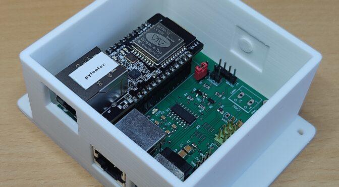
Board version with Pylontech setup
Version with OpenDTU and NRF24L01 setup

The device setups shown in the picture are equipped with a housing. I have published the “.stl” files created with FreeCad on thingiverse.

Link to thingiverse files

Here is the adapted code for use with the WT32-ETH01 board:

The “TimerConfig.h” file must be created. The file must contain the following content:

// TimerConfig.h
#ifndef TIMERCONFIG_H
#define TIMERCONFIG_H
#define TIMER_BASE_CLK 80000000
#endif // TIMERCONFIG_H

Once the file has been created, it should be located in the directory of the main program. Here is the main program:

 //Pylontec2MQTT interface  
 //code by https://github.com/irekzielinski/Pylontech-Battery-Monitoring  
 //  and https://github.com/hidaba/PylontechMonitoring  
 // the original code used WEMOS Boards with ESP8266  
 // code changed to use with WT32-ETH01 Board for use with LAN connection  
 // changes by ingmarsretro 01/2025  
 #include <ETH.h>  
 #include <WiFi.h>  
 #include <ESPmDNS.h>  
 #include <ArduinoOTA.h>  
 #include <WebServer.h>  
 #include <circular_log.h>  
 #include <ArduinoJson.h>  
 #include <NTPClient.h>  
 #include "TimerConfig.h"  
 #include <ESP32TimerInterrupt.h>  
 //+++ START CONFIGURATION +++  
 #define LED 12  
 #define RXD2 5  
 #define TXD2 17  
 #define HOSTNAME "mppsolar-pylontec"  
 #define STATIC_IP  
 IPAddress local_IP(192, 168, xx, yy);  
 IPAddress subnet(255, 255, 255, 0);  
 IPAddress gateway(192, 168, yy, zz);  
 IPAddress primaryDNS(192, 168, yy, ww);  
 //Uncomment for authentication page  
 //#define AUTHENTICATION  
 const char* www_username = "admin";  
 const char* www_password = "password";  
 //IMPORTANT: Uncomment this line if you want to enable MQTT (and fill correct MQTT_ values below):  
 #define ENABLE_MQTT  
 // Set offset time in seconds to adjust for your timezone, for example:  
 // GMT +1 = 3600  
 // GMT 0 = 0  
 #define GMT 3600  
 //NOTE 1: if you want to change what is pushed via MQTT - edit function: pushBatteryDataToMqtt.  
 //NOTE 2: MQTT_TOPIC_ROOT is where battery will push MQTT topics. For example "soc" will be pushed to: "home/grid_battery/soc"  
 #define MQTT_SERVER    "192.168.aa.bb"  
 #define MQTT_PORT     1883  
 #define MQTT_USER     ""  
 #define MQTT_PASSWORD   ""  
 #define MQTT_TOPIC_ROOT  "ingmarsretro/pylontec/" //this is where mqtt data will be pushed  
 #define MQTT_PUSH_FREQ_SEC 2 //maximum mqtt update frequency in seconds  
 //+++  END CONFIGURATION +++  
 #ifdef ENABLE_MQTT  
 #include <PubSubClient.h>  
 WiFiClient ethClient;  
 PubSubClient mqttClient(ethClient);  
 #endif //ENABLE_MQTT  
 //text response  
 char g_szRecvBuff[7000];  
 const long utcOffsetInSeconds = GMT;  
 char daysOfTheWeek[7][12] = {"Sunday", "Monday", "Tuesday", "Wednesday", "Thursday", "Friday", "Saturday"};  
 // Define NTP Client to get time  
 WiFiUDP ntpUDP;  
 NTPClient timeClient(ntpUDP, "pool.ntp.org", utcOffsetInSeconds);  
 //ESP8266WebServer server(80);  
 WebServer server(80);  
 circular_log<7000> g_log;  
 bool ntpTimeReceived = false;  
 int g_baudRate = 0;  
 void Log(const char* msg)  
 {  
  g_log.Log(msg);  
 }  
 //Define Interrupt Timer to Calculate Power meter every second (kWh)  
 #define USING_TIM_DIV1 true                       // for shortest and most accurate timer  
 //ESP8266Timer ITimer;  
 ESP32Timer ITimer(0); // Use timer 0  
 bool setInterval(unsigned long interval, timer_callback callback);   // interval (in microseconds)  
 #define TIMER_INTERVAL_MS 1000  
 //Global Variables for the Power Meter - accessible from the calculating interrupt und from main  
 unsigned long powerIN = 0;    //WS gone in to the BAttery  
 unsigned long powerOUT = 0;   //WS gone out of the Battery  
 //Global Variables for the Power Meter - Überlauf  
 unsigned long powerINWh = 0;    //WS gone in to the BAttery  
 unsigned long powerOUTWh = 0;   //WS gone out of the Battery  
 void setup() {  
  memset(g_szRecvBuff, 0, sizeof(g_szRecvBuff)); //clean variable  
  pinMode(LED, OUTPUT);   
  //digitalWrite(LED, HIGH);//high is off  
  digitalWrite(LED, LOW);//low is off  
  // put your setup code here, to run once:  
  //WiFi.mode(WIFI_STA);  
  //WiFi.persistent(false); //our credentialss are hardcoded, so we don't need ESP saving those each boot (will save on flash wear)  
  //WiFi.hostname(HOSTNAME);  
  ETH.begin();  
  ETH.setHostname(HOSTNAME);  
   #ifdef STATIC_IP  
    ETH.config(local_IP, gateway, subnet, primaryDNS);  
  #endif  
  for(int ix=0; ix<10; ix++)  
  {  
   Log("Wait for LAN Connection");  
   if (ETH.linkUp()) {  
     Serial2.println("Ethernet connected");  
     Serial2.print("IP Address: ");  
     Serial2.println(ETH.localIP());  
   } else {  
     Serial2.println("Failed to connect to Ethernet");  
   }  
   delay(1000);  
  }  
  ArduinoOTA.setHostname(HOSTNAME);  
  ArduinoOTA.begin();  
  server.on("/", handleRoot);  
  server.on("/log", handleLog);  
  server.on("/req", handleReq);  
  server.on("/jsonOut", handleJsonOut);  
  server.on("/reboot", [](){  
   #ifdef AUTHENTICATION  
   if (!server.authenticate(www_username, www_password)) {  
    return server.requestAuthentication();  
   }  
   #endif  
   ESP.restart();  
  });  
  server.begin();   
  timeClient.begin();  
 #ifdef ENABLE_MQTT  
  mqttClient.setServer(MQTT_SERVER, MQTT_PORT);  
 #endif  
  Log("Boot event");  
 }  
 void handleLog()  
 {  
  #ifdef AUTHENTICATION  
  if (!server.authenticate(www_username, www_password)) {  
   return server.requestAuthentication();  
  }   
  #endif  
  server.send(200, "text/html", g_log.c_str());  
 }  
 void switchBaud(int newRate)  
 {  
  if(g_baudRate == newRate)  
  {  
   return;  
  }  
  if(g_baudRate != 0)  
  {  
   Serial2.flush();  
   delay(20);  
   Serial2.end();  
   delay(20);  
  }  
  char szMsg[50];  
  snprintf(szMsg, sizeof(szMsg)-1, "New baud: %d", newRate);  
  Log(szMsg);  
  Serial2.begin(newRate,SERIAL_8N1, RXD2, TXD2);  
  g_baudRate = newRate;  
  delay(20);  
 }  
 void waitForSerial()  
 {  
  for(int ix=0; ix<150;ix++)  
  {  
   if(Serial2.available()) break;  
   delay(10);  
  }  
 }  
 int readFromSerial()  
 {  
  memset(g_szRecvBuff, 0, sizeof(g_szRecvBuff));  
  int recvBuffLen = 0;  
  bool foundTerminator = true;  
  waitForSerial();  
  while(Serial2.available())  
  {  
   char szResponse[256] = "";  
   const int readNow = Serial2.readBytesUntil('>', szResponse, sizeof(szResponse)-1); //all commands terminate with "$$\r\n\rpylon>" (no new line at the end)  
   if(readNow > 0 &&   
     szResponse[0] != '\0')  
   {  
    if(readNow + recvBuffLen + 1 >= (int)(sizeof(g_szRecvBuff)))  
    {  
     Log("WARNING: Read too much data on the console!");  
     break;  
    }  
    strcat(g_szRecvBuff, szResponse);  
    recvBuffLen += readNow;  
    if(strstr(g_szRecvBuff, "$$\r\n\rpylon"))  
    {  
     strcat(g_szRecvBuff, ">"); //readBytesUntil will skip this, so re-add  
     foundTerminator = true;  
     break; //found end of the string  
    }  
    if(strstr(g_szRecvBuff, "Press [Enter] to be continued,other key to exit"))  
    {  
     //we need to send new line character so battery continues the output  
     Serial2.write("\r");  
    }  
    waitForSerial();  
   }  
  }  
  if(recvBuffLen > 0 )  
  {  
   if(foundTerminator == false)  
   {  
    Log("Failed to find pylon> terminator");  
   }  
  }  
  return recvBuffLen;  
 }  
 bool readFromSerialAndSendResponse()  
 {  
  const int recvBuffLen = readFromSerial();  
  if(recvBuffLen > 0)  
  {  
   server.sendContent(g_szRecvBuff);  
   return true;  
  }  
  return false;  
 }  
 bool sendCommandAndReadSerialResponse(const char* pszCommand)  
 {  
  switchBaud(115200);  
  if(pszCommand[0] != '\0')  
  {  
   Serial2.write(pszCommand);  
  }  
  Serial2.write("\n");  
  const int recvBuffLen = readFromSerial();  
  if(recvBuffLen > 0)  
  {  
   return true;  
  }  
  //wake up console and try again:  
  wakeUpConsole();  
  if(pszCommand[0] != '\0')  
  {  
   Serial2.write(pszCommand);  
  }  
  Serial2.write("\n");  
  return readFromSerial() > 0;  
 }  
 void handleReq()  
 {  
  #ifdef AUTHENTICATION  
  if (!server.authenticate(www_username, www_password)) {  
   return server.requestAuthentication();  
  }  
  #endif  
  bool respOK;  
  if(server.hasArg("code") == false)  
  {  
   respOK = sendCommandAndReadSerialResponse("");  
  }  
  else  
  {  
   respOK = sendCommandAndReadSerialResponse(server.arg("code").c_str());  
  }  
  handleRoot();  
 }  
 void handleJsonOut()  
 {  
  #ifdef AUTHENTICATION  
  if (!server.authenticate(www_username, www_password)) {  
   return server.requestAuthentication();  
  }  
  #endif  
  if(sendCommandAndReadSerialResponse("pwr") == false)  
  {  
   server.send(500, "text/plain", "Failed to get response to 'pwr' command");  
   return;  
  }  
  parsePwrResponse(g_szRecvBuff);  
  prepareJsonOutput(g_szRecvBuff, sizeof(g_szRecvBuff));  
  server.send(200, "application/json", g_szRecvBuff);  
 }  
 void handleRoot() {  
  #ifdef AUTHENTICATION  
  if (!server.authenticate(www_username, www_password)) {  
   return server.requestAuthentication();  
  }  
  #endif  
  timeClient.update(); //get ntp datetime  
  unsigned long days = 0, hours = 0, minutes = 0;  
  unsigned long val = os_getCurrentTimeSec();  
  days = val / (3600*24);  
  val -= days * (3600*24);  
  hours = val / 3600;  
  val -= hours * 3600;  
  minutes = val / 60;  
  val -= minutes*60;  
  time_t epochTime = timeClient.getEpochTime();  
  String formattedTime = timeClient.getFormattedTime();  
  //Get a time structure  
  struct tm *ptm = gmtime ((time_t *)&epochTime);   
  int currentMonth = ptm->tm_mon+1;  
  static char szTmp[9500] = "";   
  long timezone= GMT / 3600;  
  snprintf(szTmp, sizeof(szTmp)-1, "<html><b>Pylontech Battery LAN Interface</b><br>Time GMT: %s (%s %d)<br>Uptime: %02d:%02d:%02d.%02d<br><br>free heap: %u<br>MQTT-Server: %s<br>MQTT-root topic: %s",   
       formattedTime, "GMT ", timezone,  
       (int)days, (int)hours, (int)minutes, (int)val,   
       ESP.getFreeHeap(),MQTT_SERVER,MQTT_TOPIC_ROOT);  
  strncat(szTmp, "<BR><a href='/log'>Runtime log</a><HR>", sizeof(szTmp)-1);  
  strncat(szTmp, "<form action='/req' method='get'>Command:<input type='text' name='code'/><input type='submit'> <a href='/req?code=pwr'>PWR</a> | <a href='/req?code=pwr%201'>Power 1</a> | <a href='/req?code=pwr%202'>Power 2</a> | <a href='/req?code=pwr%203'>Power 3</a> | <a href='/req?code=pwr%204'>Power 4</a> | <a href='/req?code=help'>Help</a> | <a href='/req?code=log'>Event Log</a> | <a href='/req?code=time'>Time</a><br>", sizeof(szTmp)-1);  
  //strncat(szTmp, "<form action='/req' method='get'>Command:<input type='text' name='code'/><input type='submit'><a href='/req?code=pwr'>Power</a> | <a href='/req?code=help'>Help</a> | <a href='/req?code=log'>Event Log</a> | <a href='/req?code=time'>Time</a><br>", sizeof(szTmp)-1);  
  strncat(szTmp, "<textarea rows='80' cols='180'>", sizeof(szTmp)-1);  
  //strncat(szTmp, "<textarea rows='45' cols='180'>", sizeof(szTmp)-1);  
  strncat(szTmp, g_szRecvBuff, sizeof(szTmp)-1);  
  strncat(szTmp, "</textarea></form>", sizeof(szTmp)-1);  
  strncat(szTmp, "</html>", sizeof(szTmp)-1);  
  //send page  
  server.send(200, "text/html", szTmp);  
 }  
 unsigned long os_getCurrentTimeSec()  
 {  
  static unsigned int wrapCnt = 0;  
  static unsigned long lastVal = 0;  
  unsigned long currentVal = millis();  
  if(currentVal < lastVal)  
  {  
   wrapCnt++;  
  }  
  lastVal = currentVal;  
  unsigned long seconds = currentVal/1000;  
  //millis will wrap each 50 days, as we are interested only in seconds, let's keep the wrap counter  
  return (wrapCnt*4294967) + seconds;  
 }  
 void wakeUpConsole()  
 {  
  switchBaud(1200);  
  //byte wakeUpBuff[] = {0x7E, 0x32, 0x30, 0x30, 0x31, 0x34, 0x36, 0x38, 0x32, 0x43, 0x30, 0x30, 0x34, 0x38, 0x35, 0x32, 0x30, 0x46, 0x43, 0x43, 0x33, 0x0D};  
  //Serial.write(wakeUpBuff, sizeof(wakeUpBuff));  
  Serial.write("~20014682C0048520FCC3\r");  
  delay(1000);  
  byte newLineBuff[] = {0x0E, 0x0A};  
  switchBaud(115200);  
  for(int ix=0; ix<10; ix++)  
  {  
   Serial.write(newLineBuff, sizeof(newLineBuff));  
   delay(1000);  
   if(Serial.available())  
   {  
    while(Serial.available())  
    {  
     Serial.read();  
    }  
    break;  
   }  
  }  
 }  
 #define MAX_PYLON_BATTERIES 8  
 struct pylonBattery  
 {  
  bool isPresent;  
  long soc;   //Coulomb in %  
  long voltage; //in mW  
  long current; //in mA, negative value is discharge  
  long tempr;  //temp of case or BMS?  
  long cellTempLow;  
  long cellTempHigh;  
  long cellVoltLow;  
  long cellVoltHigh;  
  char baseState[9];  //Charge | Dischg | Idle  
  char voltageState[9]; //Normal  
  char currentState[9]; //Normal  
  char tempState[9];  //Normal  
  char time[20];    //2019-06-08 04:00:29  
  char b_v_st[9];    //Normal (battery voltage?)  
  char b_t_st[9];    //Normal (battery temperature?)  
  bool isCharging()  const { return strcmp(baseState, "Charge")  == 0; }  
  bool isDischarging() const { return strcmp(baseState, "Dischg")  == 0; }  
  bool isIdle()    const { return strcmp(baseState, "Idle")   == 0; }  
  bool isBalancing()  const { return strcmp(baseState, "Balance") == 0; }  
  bool isNormal() const  
  {  
   if(isCharging()  == false &&  
     isDischarging() == false &&  
     isIdle()    == false &&  
     isBalancing()  == false)  
   {  
    return false; //base state looks wrong!  
   }  
   return strcmp(voltageState, "Normal") == 0 &&  
       strcmp(currentState, "Normal") == 0 &&  
       strcmp(tempState,  "Normal") == 0 &&  
       strcmp(b_v_st,    "Normal") == 0 &&  
       strcmp(b_t_st,    "Normal") == 0 ;  
  }  
 };  
 struct batteryStack  
 {  
  int batteryCount;  
  int soc; //in %, if charging: average SOC, otherwise: lowest SOC  
  int temp; //in mC, if highest temp is > 15C, this will show the highest temp, otherwise the lowest  
  long currentDC;  //mAh current going in or out of the battery  
  long avgVoltage;  //in mV  
  char baseState[9]; //Charge | Dischg | Idle | Balance | Alarm!  
  pylonBattery batts[MAX_PYLON_BATTERIES];  
  bool isNormal() const  
  {  
   for(int ix=0; ix<MAX_PYLON_BATTERIES; ix++)  
   {  
    if(batts[ix].isPresent &&   
      batts[ix].isNormal() == false)  
    {  
     return false;  
    }  
   }  
   return true;  
  }  
  //in Wh  
  long getPowerDC() const  
  {  
   return (long)(((double)currentDC/1000.0)*((double)avgVoltage/1000.0));  
  }  
  // power in Wh in charge  
  float powerIN() const  
  {  
   if (currentDC > 0) {  
     return (float)(((double)currentDC/1000.0)*((double)avgVoltage/1000.0));  
   } else {  
     return (float)(0);  
   }  
  }  
  // power in Wh in discharge  
  float powerOUT() const  
  {  
   if (currentDC < 0) {  
     return (float)(((double)currentDC/1000.0)*((double)avgVoltage/1000.0)*-1);  
   } else {  
     return (float)(0);  
   }  
  }  
  //Wh estimated current on AC side (taking into account Sofar ME3000SP losses)  
  long getEstPowerAc() const  
  {  
   double powerDC = (double)getPowerDC();  
   if(powerDC == 0)  
   {  
    return 0;  
   }  
   else if(powerDC < 0)  
   {  
    //we are discharging, on AC side we will see less power due to losses  
    if(powerDC < -1000)  
    {  
     return (long)(powerDC*0.94);  
    }  
    else if(powerDC < -600)  
    {  
     return (long)(powerDC*0.90);  
    }  
    else  
    {  
     return (long)(powerDC*0.87);  
    }  
   }  
   else  
   {  
    //we are charging, on AC side we will have more power due to losses  
    if(powerDC > 1000)  
    {  
     return (long)(powerDC*1.06);  
    }  
    else if(powerDC > 600)  
    {  
     return (long)(powerDC*1.1);  
    }  
    else  
    {  
     return (long)(powerDC*1.13);  
    }  
   }  
  }  
 };  
 batteryStack g_stack;  
 long extractInt(const char* pStr, int pos)  
 {  
  return atol(pStr+pos);  
 }  
 void extractStr(const char* pStr, int pos, char* strOut, int strOutSize)  
 {  
  strOut[strOutSize-1] = '\0';  
  strncpy(strOut, pStr+pos, strOutSize-1);  
  strOutSize--;  
  //trim right  
  while(strOutSize > 0)  
  {  
   if(isspace(strOut[strOutSize-1]))  
   {  
    strOut[strOutSize-1] = '\0';  
   }  
   else  
   {  
    break;  
   }  
   strOutSize--;  
  }  
 }  
 /* Output has mixed \r and \r\n  
 pwr  
 @  
 Power Volt  Curr  Tempr Tlow  Thigh Vlow  Vhigh Base.St Volt.St Curr.St Temp.St Coulomb Time         B.V.St  B.T.St   
 1   49735 -1440 22000 19000 19000 3315  3317  Dischg  Normal  Normal  Normal  93%   2019-06-08 04:00:30 Normal  Normal   
 ....    
 8   -   -   -   -   -   -   -   Absent  -    -    -    -    -          -    -      
 Command completed successfully  
 $$  
 pylon  
 */  
 bool parsePwrResponse(const char* pStr)  
 {  
  if(strstr(pStr, "Command completed successfully") == NULL)  
  {  
   return false;  
  }  
  int chargeCnt  = 0;  
  int dischargeCnt = 0;  
  int idleCnt   = 0;  
  int alarmCnt   = 0;  
  int socAvg    = 0;  
  int socLow    = 0;  
  int tempHigh   = 0;  
  int tempLow   = 0;  
  memset(&g_stack, 0, sizeof(g_stack));  
  for(int ix=0; ix<MAX_PYLON_BATTERIES; ix++)  
  {  
   char szToFind[32] = "";  
   snprintf(szToFind, sizeof(szToFind)-1, "\r\r\n%d   ", ix+1);  
   const char* pLineStart = strstr(pStr, szToFind);  
   if(pLineStart == NULL)  
   {  
    return false;  
   }  
   pLineStart += 3; //move past \r\r\n  
   extractStr(pLineStart, 55, g_stack.batts[ix].baseState, sizeof(g_stack.batts[ix].baseState));  
   if(strcmp(g_stack.batts[ix].baseState, "Absent") == 0)  
   {  
    g_stack.batts[ix].isPresent = false;  
   }  
   else  
   {  
    g_stack.batts[ix].isPresent = true;  
    extractStr(pLineStart, 64, g_stack.batts[ix].voltageState, sizeof(g_stack.batts[ix].voltageState));  
    extractStr(pLineStart, 73, g_stack.batts[ix].currentState, sizeof(g_stack.batts[ix].currentState));  
    extractStr(pLineStart, 82, g_stack.batts[ix].tempState, sizeof(g_stack.batts[ix].tempState));  
    extractStr(pLineStart, 100, g_stack.batts[ix].time, sizeof(g_stack.batts[ix].time));  
    extractStr(pLineStart, 121, g_stack.batts[ix].b_v_st, sizeof(g_stack.batts[ix].b_v_st));  
    extractStr(pLineStart, 130, g_stack.batts[ix].b_t_st, sizeof(g_stack.batts[ix].b_t_st));  
    g_stack.batts[ix].voltage = extractInt(pLineStart, 6);  
    g_stack.batts[ix].current = extractInt(pLineStart, 13);  
    g_stack.batts[ix].tempr  = extractInt(pLineStart, 20);  
    g_stack.batts[ix].cellTempLow  = extractInt(pLineStart, 27);  
    g_stack.batts[ix].cellTempHigh  = extractInt(pLineStart, 34);  
    g_stack.batts[ix].cellVoltLow  = extractInt(pLineStart, 41);  
    g_stack.batts[ix].cellVoltHigh  = extractInt(pLineStart, 48);  
    g_stack.batts[ix].soc      = extractInt(pLineStart, 91);  
    //////////////////////////////// Post-process ////////////////////////  
    g_stack.batteryCount++;  
    g_stack.currentDC += g_stack.batts[ix].current;  
    g_stack.avgVoltage += g_stack.batts[ix].voltage;  
    socAvg += g_stack.batts[ix].soc;  
    if(g_stack.batts[ix].isNormal() == false){ alarmCnt++; }  
    else if(g_stack.batts[ix].isCharging()){chargeCnt++;}  
    else if(g_stack.batts[ix].isDischarging()){dischargeCnt++;}  
    else if(g_stack.batts[ix].isIdle()){idleCnt++;}  
    else{ alarmCnt++; } //should not really happen!  
    if(g_stack.batteryCount == 1)  
    {  
     socLow = g_stack.batts[ix].soc;  
     tempLow = g_stack.batts[ix].cellTempLow;  
     tempHigh = g_stack.batts[ix].cellTempHigh;  
    }  
    else  
    {  
     if(socLow > g_stack.batts[ix].soc){socLow = g_stack.batts[ix].soc;}  
     if(tempHigh < g_stack.batts[ix].cellTempHigh){tempHigh = g_stack.batts[ix].cellTempHigh;}  
     if(tempLow > g_stack.batts[ix].cellTempLow){tempLow = g_stack.batts[ix].cellTempLow;}  
    }  
   }  
  }  
  //now update stack state:  
  g_stack.avgVoltage /= g_stack.batteryCount;  
  g_stack.soc = socLow;  
  if(tempHigh > 15000) //15C  
  {  
   g_stack.temp = tempHigh; //in the summer we highlight the warmest cell  
  }  
  else  
  {  
   g_stack.temp = tempLow; //in the winter we focus on coldest cell  
  }  
  if(alarmCnt > 0)  
  {  
   strcpy(g_stack.baseState, "Alarm!");  
  }  
  else if(chargeCnt == g_stack.batteryCount)  
  {  
   strcpy(g_stack.baseState, "Charge");  
   g_stack.soc = (int)(socAvg / g_stack.batteryCount);  
  }  
  else if(dischargeCnt == g_stack.batteryCount)  
  {  
   strcpy(g_stack.baseState, "Dischg");  
  }  
  else if(idleCnt == g_stack.batteryCount)  
  {  
   strcpy(g_stack.baseState, "Idle");  
  }  
  else  
  {  
   strcpy(g_stack.baseState, "Balance");  
  }  
  return true;  
 }  
 void prepareJsonOutput(char* pBuff, int buffSize)  
 {  
  memset(pBuff, 0, buffSize);  
  snprintf(pBuff, buffSize-1, "{\"soc\": %d, \"temp\": %d, \"currentDC\": %ld, \"avgVoltage\": %ld, \"baseState\": \"%s\", \"batteryCount\": %d, \"powerDC\": %ld, \"estPowerAC\": %ld, \"isNormal\": %s}", g_stack.soc,   
                                                                                                       g_stack.temp,   
                                                                                                       g_stack.currentDC,   
                                                                                                       g_stack.avgVoltage,   
                                                                                                       g_stack.baseState,   
                                                                                                       g_stack.batteryCount,   
                                                                                                       g_stack.getPowerDC(),   
                                                                                                       g_stack.getEstPowerAc(),  
                                                                                                       g_stack.isNormal() ? "true" : "false");  
 }  
 void loop() {  
 #ifdef ENABLE_MQTT  
  mqttLoop();  
 #endif  
  ArduinoOTA.handle();  
  server.handleClient();  
  //if there are bytes availbe on serial here - it's unexpected  
  //when we send a command to battery, we read whole response  
  //if we get anything here anyways - we will log it  
  int bytesAv = Serial.available();  
  if(bytesAv > 0)  
  {  
   if(bytesAv > 63)  
   {  
    bytesAv = 63;  
   }  
   char buff[64+4] = "RCV:";  
   if(Serial.readBytes(buff+4, bytesAv) > 0)  
   {  
    //digitalWrite(LED, LOW);  
    digitalWrite(LED, HIGH);  
    delay(5);  
    //digitalWrite(LED, HIGH);//high is off  
    digitalWrite(LED, LOW);  
    Log(buff);  
   }  
  }  
 }  
 #ifdef ENABLE_MQTT  
 #define ABS_DIFF(a, b) (a > b ? a-b : b-a)  
 void mqtt_publish_f(const char* topic, float newValue, float oldValue, float minDiff, bool force)  
 {  
  char szTmp[16] = "";  
  snprintf(szTmp, 15, "%.2f", newValue);  
  if(force || ABS_DIFF(newValue, oldValue) > minDiff)  
  {  
   mqttClient.publish(topic, szTmp, false);  
  }  
 }  
 void mqtt_publish_i(const char* topic, int newValue, int oldValue, int minDiff, bool force)  
 {  
  char szTmp[16] = "";  
  snprintf(szTmp, 15, "%d", newValue);  
  if(force || ABS_DIFF(newValue, oldValue) > minDiff)  
  {  
   mqttClient.publish(topic, szTmp, false);  
  }  
 }  
 void mqtt_publish_s(const char* topic, const char* newValue, const char* oldValue, bool force)  
 {  
  if(force || strcmp(newValue, oldValue) != 0)  
  {  
   mqttClient.publish(topic, newValue, false);  
  }  
 }  
 void pushBatteryDataToMqtt(const batteryStack& lastSentData, bool forceUpdate /* if true - we will send all data regardless if it's the same */)  
 {  
  mqtt_publish_f(MQTT_TOPIC_ROOT "soc",     g_stack.soc,        lastSentData.soc,        0, forceUpdate);  
  mqtt_publish_f(MQTT_TOPIC_ROOT "temp",     (float)g_stack.temp/1000.0, (float)lastSentData.temp/1000.0, 0.1, forceUpdate);  
  mqtt_publish_i(MQTT_TOPIC_ROOT "currentDC",  g_stack.currentDC,     lastSentData.currentDC,     1, forceUpdate);  
  mqtt_publish_i(MQTT_TOPIC_ROOT "estPowerAC",  g_stack.getEstPowerAc(),  lastSentData.getEstPowerAc(),  10, forceUpdate);  
  mqtt_publish_i(MQTT_TOPIC_ROOT "battery_count",g_stack.batteryCount,    lastSentData.batteryCount,    0, forceUpdate);  
  mqtt_publish_s(MQTT_TOPIC_ROOT "base_state",  g_stack.baseState,     lastSentData.baseState      , forceUpdate);  
  mqtt_publish_i(MQTT_TOPIC_ROOT "is_normal",  g_stack.isNormal() ? 1:0,  lastSentData.isNormal() ? 1:0,  0, forceUpdate);  
  mqtt_publish_i(MQTT_TOPIC_ROOT "getPowerDC",  g_stack.getPowerDC(),    lastSentData.getPowerDC(),    1, forceUpdate);  
  mqtt_publish_i(MQTT_TOPIC_ROOT "powerIN",   g_stack.powerIN(),     lastSentData.powerIN(),     1, forceUpdate);  
  mqtt_publish_i(MQTT_TOPIC_ROOT "powerOUT",   g_stack.powerOUT(),     lastSentData.powerOUT(),     1, forceUpdate);  
  // publishing details  
  for (int ix = 0; ix < g_stack.batteryCount; ix++) {  
   char ixBuff[50];  
   String ixBattStr = MQTT_TOPIC_ROOT + String(ix) + "/voltage";  
   ixBattStr.toCharArray(ixBuff, 50);  
   mqtt_publish_f(ixBuff, g_stack.batts[ix].voltage / 1000.0, lastSentData.batts[ix].voltage / 1000.0, 0, forceUpdate);  
   ixBattStr = MQTT_TOPIC_ROOT + String(ix) + "/current";  
   ixBattStr.toCharArray(ixBuff, 50);  
   mqtt_publish_f(ixBuff, g_stack.batts[ix].current / 1000.0, lastSentData.batts[ix].current / 1000.0, 0, forceUpdate);  
   ixBattStr = MQTT_TOPIC_ROOT + String(ix) + "/soc";  
   ixBattStr.toCharArray(ixBuff, 50);  
   mqtt_publish_i(ixBuff, g_stack.batts[ix].soc, lastSentData.batts[ix].soc, 0, forceUpdate);  
   ixBattStr = MQTT_TOPIC_ROOT + String(ix) + "/charging";  
   ixBattStr.toCharArray(ixBuff, 50);  
   mqtt_publish_i(ixBuff, g_stack.batts[ix].isCharging()?1:0, lastSentData.batts[ix].isCharging()?1:0, 0, forceUpdate);  
   ixBattStr = MQTT_TOPIC_ROOT + String(ix) + "/discharging";  
   ixBattStr.toCharArray(ixBuff, 50);  
   mqtt_publish_i(ixBuff, g_stack.batts[ix].isDischarging()?1:0, lastSentData.batts[ix].isDischarging()?1:0, 0, forceUpdate);  
   ixBattStr = MQTT_TOPIC_ROOT + String(ix) + "/idle";  
   ixBattStr.toCharArray(ixBuff, 50);  
   mqtt_publish_i(ixBuff, g_stack.batts[ix].isIdle()?1:0, lastSentData.batts[ix].isIdle()?1:0, 0, forceUpdate);  
   ixBattStr = MQTT_TOPIC_ROOT + String(ix) + "/state";  
   ixBattStr.toCharArray(ixBuff, 50);  
   mqtt_publish_s(ixBuff, g_stack.batts[ix].isIdle()?"Idle":g_stack.batts[ix].isCharging()?"Charging":g_stack.batts[ix].isDischarging()?"Discharging":"", lastSentData.batts[ix].isIdle()?"Idle":lastSentData.batts[ix].isCharging()?"Charging":lastSentData.batts[ix].isDischarging()?"Discharging":"", forceUpdate);  
   ixBattStr = MQTT_TOPIC_ROOT + String(ix) + "/temp";  
   ixBattStr.toCharArray(ixBuff, 50);  
   mqtt_publish_f(ixBuff, (float)g_stack.batts[ix].tempr/1000.0, (float)lastSentData.batts[ix].tempr/1000.0, 0.1, forceUpdate);  
  }  
 }   
 void mqttLoop()  
 {  
  //if we have problems with connecting to mqtt server, we will attempt to re-estabish connection each 1minute (not more than that)  
  static unsigned long g_lastConnectionAttempt = 0;  
  //first: let's make sure we are connected to mqtt  
  const char* topicLastWill = MQTT_TOPIC_ROOT "availability";  
  if (!mqttClient.connected() && (g_lastConnectionAttempt == 0 || os_getCurrentTimeSec() - g_lastConnectionAttempt > 60)) {  
   if(mqttClient.connect(HOSTNAME, MQTT_USER, MQTT_PASSWORD, topicLastWill, 1, true, "offline"))  
   {  
    Log("Connected to MQTT server: " MQTT_SERVER);  
    mqttClient.publish(topicLastWill, "online", true);  
   }  
   else  
   {  
    Log("Failed to connect to MQTT server.");  
   }  
   g_lastConnectionAttempt = os_getCurrentTimeSec();  
  }  
  //next: read data from battery and send via MQTT (but only once per MQTT_PUSH_FREQ_SEC seconds)  
  static unsigned long g_lastDataSent = 0;  
  if(mqttClient.connected() &&   
    os_getCurrentTimeSec() - g_lastDataSent > MQTT_PUSH_FREQ_SEC &&  
    sendCommandAndReadSerialResponse("pwr") == true)  
  {  
   static batteryStack lastSentData; //this is the last state we sent to MQTT, used to prevent sending the same data over and over again  
   static unsigned int callCnt = 0;  
   parsePwrResponse(g_szRecvBuff);  
   bool forceUpdate = (callCnt % 20 == 0); //push all the data every 20th call  
   pushBatteryDataToMqtt(lastSentData, forceUpdate);  
   callCnt++;  
   g_lastDataSent = os_getCurrentTimeSec();  
   memcpy(&lastSentData, &g_stack, sizeof(batteryStack));  
  }  
  mqttClient.loop();  
 }  
 #endif //ENABLE_MQTT