![]()
edit 7.11.24
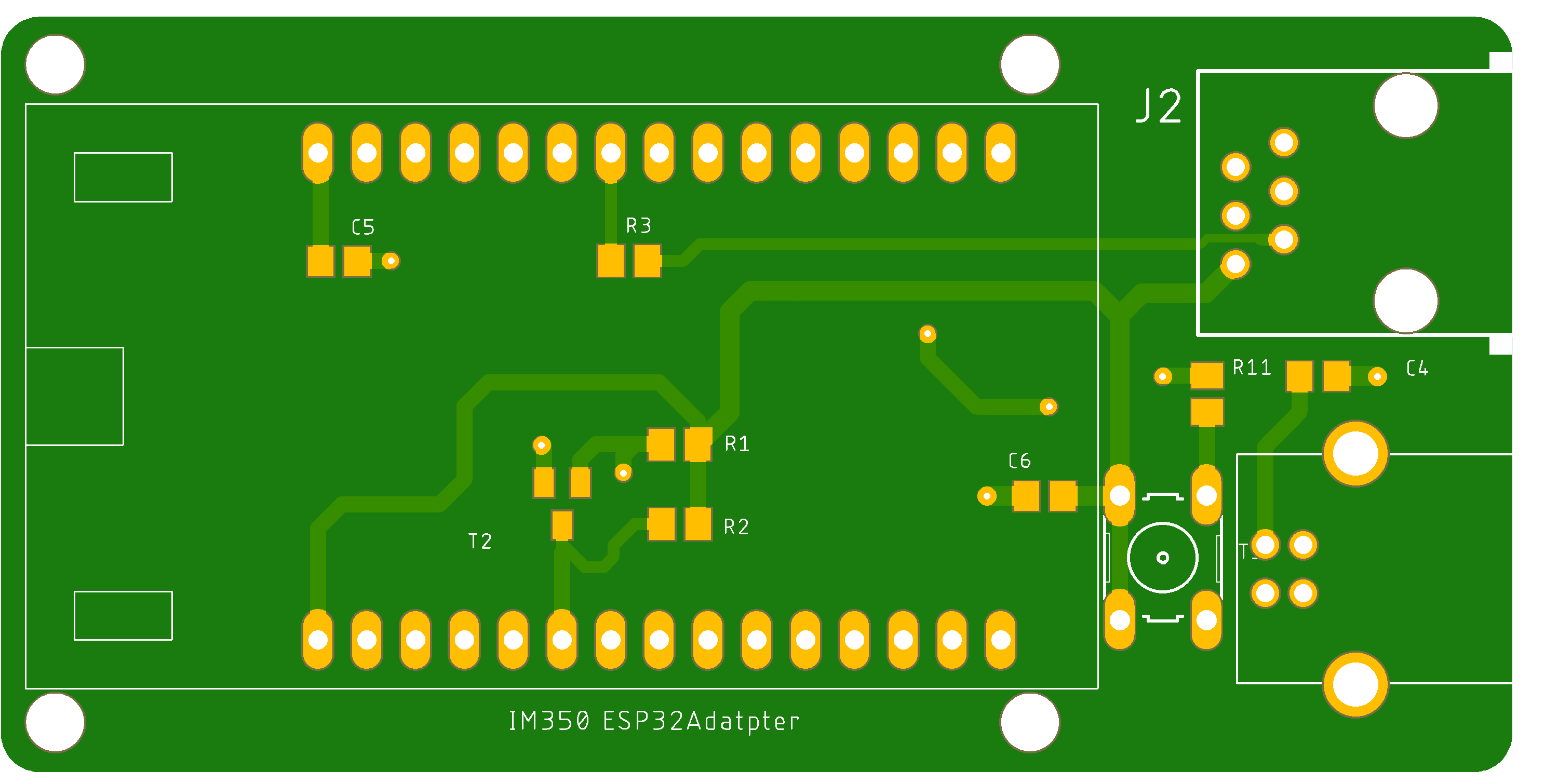
In the meantime, I have also layouted an interface board with a USB type B socket for the 5V supply. (see layout below). Because as small and fine as the micro USB plugs are, I need something more robust.
As I am asked more and more often for the production data, I am making the Gerber data of the circuit boards available for download:
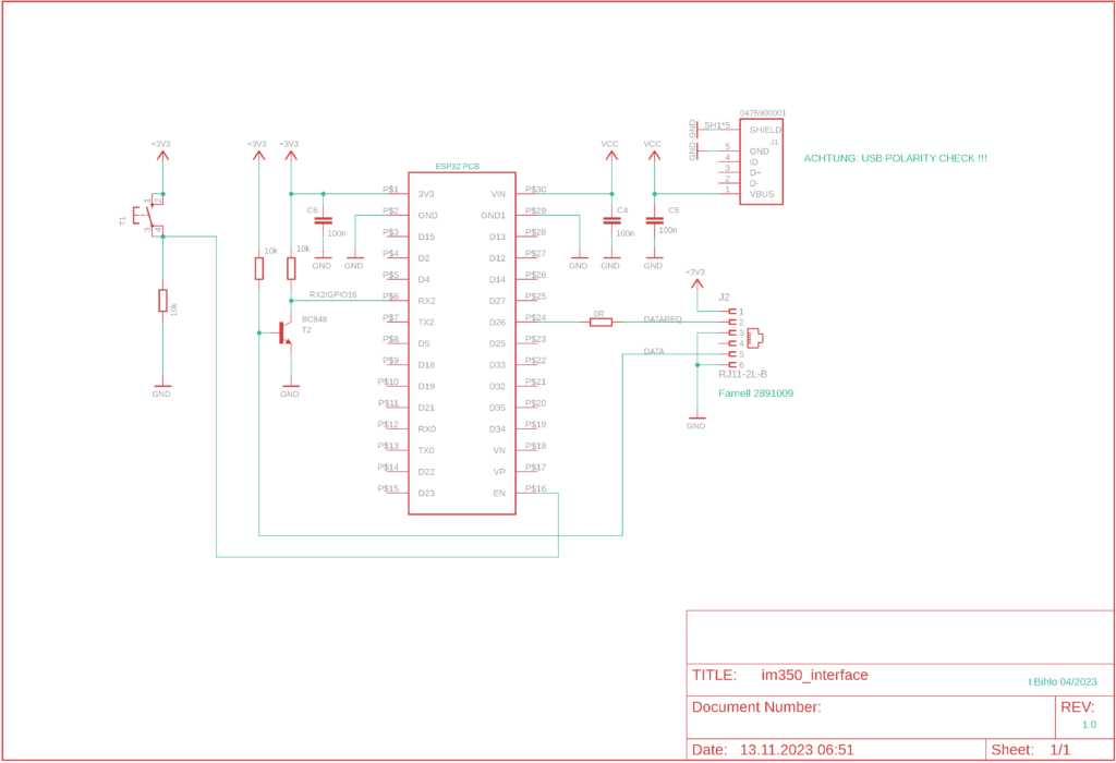
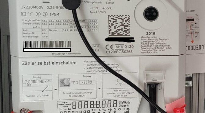
In the article entitled: “Reading energy supply company smart meters with ESP32 and sending data via MQTT” (link), I described how the energy supply companies’ smart meters can be read out via the customer interface. The measurement data is then available as topics via the mqtt broker and can be further processed in various home automation systems (HomeMatic, Homeassistant, etc.). All you need is an ESP32 board and a few small parts to establish the connection to the smart meter. As a small update, I have now embellished the structure (back then with pin headers on a breadboard) a little and made a circuit board.
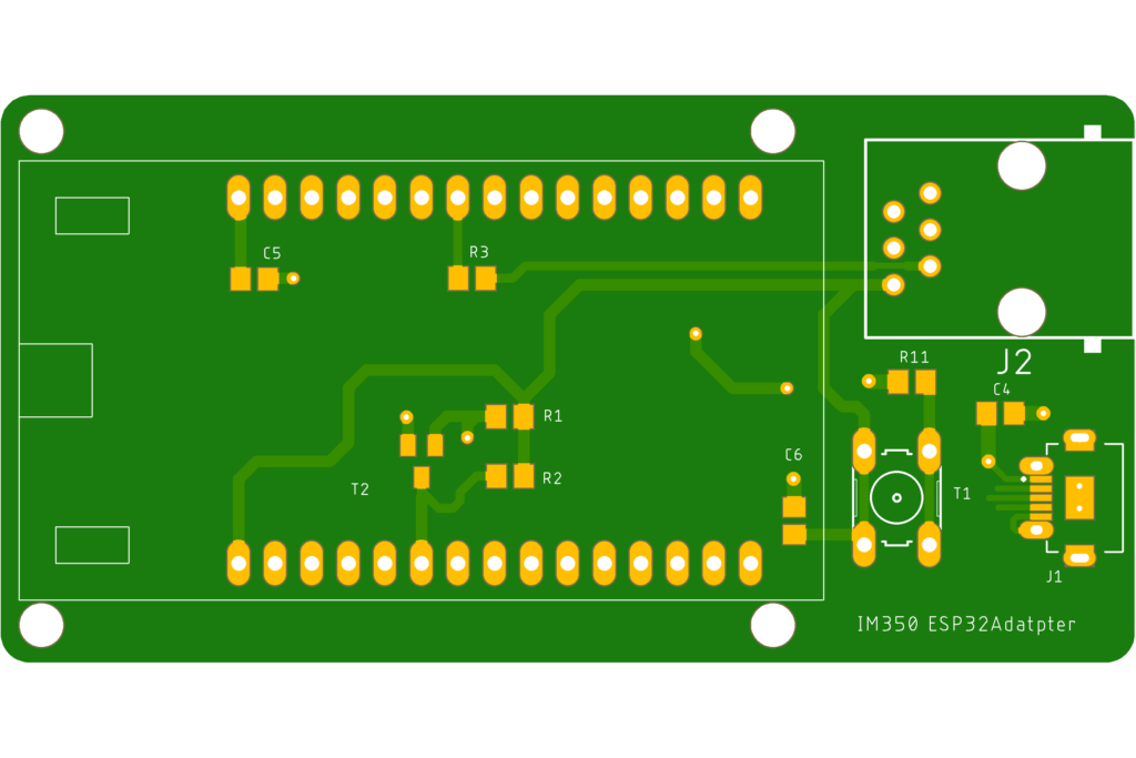
The associated circuit diagram essentially corresponds to the sketch in the previous article. To make things a little more convenient with the new circuit board, the connection to the customer interface of the smart meter can be plugged in via an RJ socket. I have also implemented the power supply via a USB socket.
Once the ESP32 circuit board had been fitted and plugged in, the device was given a small housing and is now doing its job in the electrical distribution cabinet.
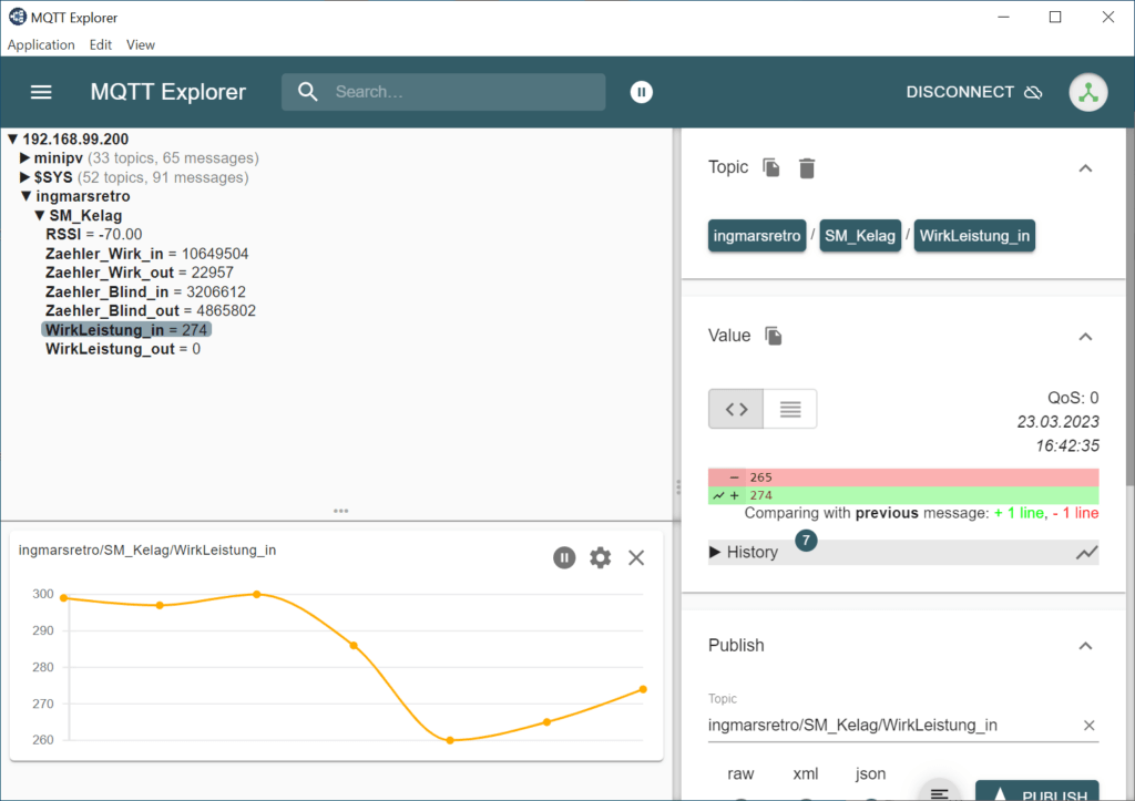
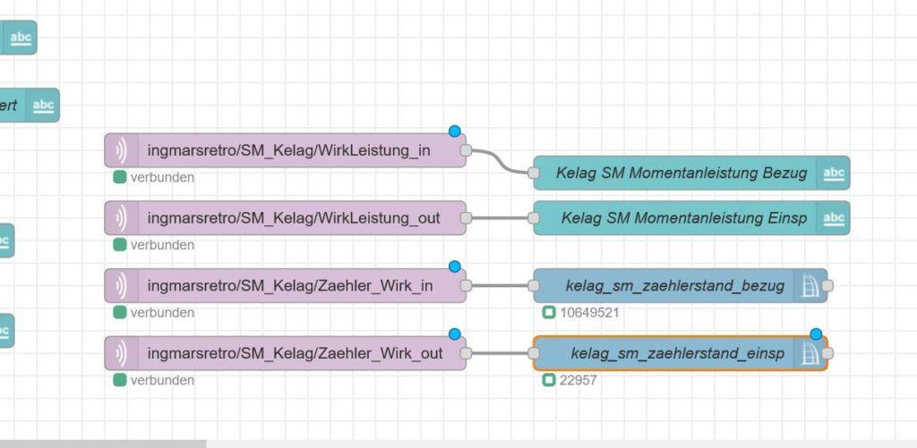
The hardware is therefore ready and functional. I have also considered changing something about the software. Until now, the ESP was running a program that decrypted the data from the smart meter and then sent it to the IP address of the broker via MQTT. However, as I am now also a user of the ESPHome integration in my HomeAssistant environment, I have flashed the ESP with an ESPHome base image. On GitHub there is the repository of Andre-Schuiki, where he publishes a version for ISKRA and SIEMENS Smartmeter for use with ESPHome. The installation instructions can be found under the following link: https://github.com/Andre-Schuiki/esphome_im350/tree/main/esp_home
The script for the ESPHome device looks like this:
 esphome:
  name: kelagsmartmeter
  friendly_name: KelagSmartmeter
  libraries:
  - "Crypto" # !IMPORTANT! we need this library for decryption!
 esp32:
  board: esp32dev
  framework:
   type: arduino
 # Enable logging
 logger:
 # Enable Home Assistant API
 api:
  encryption:
   key: "da kommt der key rein des neu angelegten ESPHome Gerätes rein"
 ota:
  password: "das automatisch generierte ota passwort"
 wifi:
  ssid: !secret wifi_ssid
  password: !secret wifi_password
  # Enable fallback hotspot (captive portal) in case wifi connection fails
  ap:
   ssid: "Kelagsmartmeter Fallback Hotspot"
   password: "das automatisch generierte password"
 captive_portal:
 external_components:
  - source:
    type: local
    path: custom_esphome
 sensor:
  - platform: siemens_im350
   update_interval: 5s
   trigger_pin: 26 # this pin goes to pin 2 of the customer interface and will be set to high before we try to read the data from the rx pin
   rx_pin: 16 # this pin goes to pin 5 of the customer interface
   tx_pin: 17 # not connected at the moment, i added it just in case we need it in the future..
   decryption_key: "00AA01BB02CC03DD04EE05FF06AA07BB" # you get the key from your provider!
   use_test_data: false # that was just for debugging, if you set it to true data are not read from serial and the test_data string is used
   test_data: "7EA077CF022313BB45E6E700DB0849534B697460B6FA5F200005C8606F536D06C32A190761E80A97E895CECA358D0A0EFD7E9C47A005C0F65B810D37FB0DA2AD6AB95F7F372F2AB11560E2971B914A5F8BFF5E06D3AEFBCD95B244A373C5DBDA78592ED2C1731488D50C0EC295E9056B306F4394CDA7D0FC7E0000"
   delay_before_reading_data: 1000 # this is needed because we have to wait for the interface to power up, you can try to lower this value but 1 sec was ok for me
   max_wait_time_for_reading_data: 1100 # maximum time to read the 123 Bytes (just in case we get no data)
   ntp_server: "pool.ntp.org" #if no ntp is specified pool.ntp.org is used
   ntp_gmt_offset: 3600
   ntp_daylight_offset: 3600
   counter_reading_p_in:
    name: reading_p_in
    filters:
     - lambda: return x / 1000;
    unit_of_measurement: kWh
    accuracy_decimals: 3
    device_class: energy
   counter_reading_p_out:
    name: reading_p_out
    filters:
     - lambda: return x / 1000;
    unit_of_measurement: kWh
    accuracy_decimals: 3
    device_class: energy
   counter_reading_q_in:
    name: reading_q_in
    filters:
     - lambda: return x / 1000;
    unit_of_measurement: kvarh
    device_class: energy
   counter_reading_q_out:
    name: reading_q_out
    filters:
     - lambda: return x / 1000;
    unit_of_measurement: kvarh
    device_class: energy
   current_power_usage_in:
    name: power_usage_in
    filters:
     - lambda: return x / 1000;
    unit_of_measurement: kW
    accuracy_decimals: 3
    device_class: energy
   current_power_usage_out:
    name: power_usage_out
    filters:
     - lambda: return x / 1000;
    unit_of_measurement: kW
    accuracy_decimals: 3
    device_class: energy
  # Extra sensor to keep track of uptime
  - platform: uptime
   name: IM350_Uptime Sensor
 switch:
  - platform: restart
   name: IM350_Restart

