Tag Archives: Walkman

Sony Walkman WM-DD11

Loading

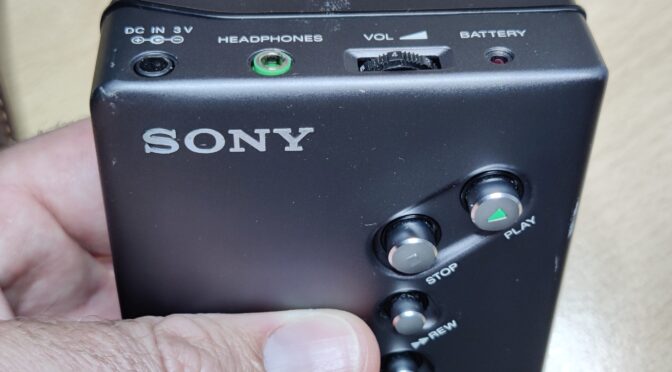
The portable cassette player from the manufacturer SONY with the type designation WM-DD11 is the content of this article. Colloquially known as “Walkman”, I received this part for my collection. Of course with the comment “defective” – ​​so again a little challenge and at the same time the hope that no mechanical, no longer available parts are affected. My request before the purchase whether there was any damage to the circuit board was also answered in the negative. The device is so far in order, the tape of an inserted cassette is moving – there is just no sound from the headphones. So ideal conditions for a restoration.

But unfortunately you cannot trust every statement and you cannot look “under the hood” beforehand and convince yourself whether the actual condition of a device corresponds to the description. When I held the part in my hands, the first impression was also very convincing. There were no noticeable scratches and dents. The area of ​​the battery compartment that was visible from the outside was also clean. So batteries inserted, also an audio cassette and then pressed on play. Lo and behold, the tape transport runs as described. Even as described, the part does not make any sound. So perfect starting conditions for my mini repair / restoration project.

But before I start dismantling, I did a little research on the history of SONY’s DD Walkman series. The first model in the DD series was sold in 1982. The designation “DD” stands for “Disc Drive”, which means that the “Disk”, i.e. the flywheel disk, is also part of the capstan drive system (motor). The belt for the other drives (tape reels) is placed directly around the disk. There are / were two price brackets of the DD models – the DD series with one-digit numbering (DD-1, DD-2, etc.) and those with two-digit numbering (DD-11, …). The devices with the single-digit number belong to the “high-end rail”. The device restored here comes from the “cheap line”. The DD-11 is not so high-quality and is also more simply constructed, but defective devices are available for very little money and are also fairly easy to repair. (The DD-11, for example, does not have a center wheel, an often defective part of the high-end series that is broken due to weak material. What then usually remains are defects in the electronics or on the mechanical side – an aged belt The belt is the same as that already installed in the legendary TPS-L2 Walkman and has the component serial number: SN 3-499-042-99 (this source or number has not been verified) You can also find the belt if you go to “TPS -L2 belt “searches on various online portals.But now enough information on the general part. I experienced a sobering and grounding of my restoration euphoria immediately after unscrewing and opening the case. Unfortunately, the circuit board is not at all undamaged. Once again someone did not remove the 1.5Volt cells and left them in the device for a very, very long time.

The batteries that leaked, as it is, have left clear marks on the circuit board. This means that extensive cleaning of the circuit board is necessary before the search for corroded conductor tracks can begin.

After cleaning and removing the battery electrolyte residues, I was able to make out a few defective conductor tracks. Fortunately, these are pretty easy to fix. In most cases it is sufficient to remove the solder resist in the defective area and to tin the exposed copper tracks. Depending on the width of the track, the defective part of the track is then reconnected with individual strands or wires.

Now the time has come to carry out a first functional test after a provisional assembly. And as described, the capstan drive works, the tape is transported – but there is no noise whatsoever from the connected speakers. Now is the time to look at the number one source of failure – the old electrolytic capacitors. Eleven of these are installed on the board.

When I removed the first electrolytic capacitor for a capacity test, the well-known fishy smell rose again. As expected, the capacitance of the capacitor was also well below the nominal value. So I made a spontaneous decision to remove all eleven electrolytic capacitors in order to swap space. (In modern language it is called “recap”: D)

The following values ​​must be renewed:
– 5 Stück 220 µF / 4V
– 1 Stück 100µF / 4V
– 3 Stück  47µF / 4V
– 1 Stück 10µF / 16V
– 1 Stück 4.7µF / 25V


I like to replace the SMD electrolytic capacitors with SMD multilayer capacitors, as these are now also available in very small designs in high capacities with suitable dielectric strength.

After the renewal, the board looks nice again. A repeated provisional commissioning shows that the effort was worth it. The music on the inserted tape sounds in the expected quality. The next step is to calibrate or adjust the belt speed. A reference tape is required for this. Years ago I recorded one with a very good tape recorder. The recording consists of a 1kHz and a 5kHz sine tone. This band is now used as a reference in the DD11. To do this, the output of the DD11 is connected to a frequency counter or oscilloscope and adjusted with the trimmer potentiometer during playback until the 1000 Hz or 5000 Hz can be seen exactly on the oscilloscope.

The Walkman can now be reassembled. All screws are properly tightened again and finally the function tested again and the beautiful piece can be put in the showcase …

DAT-Walkman Sony TCD-D3

Loading

Sony TCD-D3

At least one blog post per month to write I have set myself the goal, even if it is not always easy to implement this temporally. Anyone who has small children himself can perhaps imagine that. But in the evening and in between, I can collect material and edit it. -> it just takes everything much longer. This time I organized a Sony DAT recorder for retro audio. It is a Sony TCD-D3 from 1990-91, a so-called DAT Walkman.

DAT (Digital Audio Tape) is an audio magnetic tape recorded digitally. The recording format and the sound quality are essentially similar to those of the audio CD. The recording takes place on small cassettes, which were also used in the storage area in the EDP (DDS tapes). The DAT format was intended as the successor of the audio cassette, could not prevail in the broad market. It is also discussed here that the music industry did not want to see the format in the consumer world, as it was possible with the system to produce digital, lossless copies.

The technical structure of the cassette drive corresponds to that of a video recorder. The tape is pulled out of the cassette with loading arms and passed around a rotating head (DAT-R). The recording is done in helical scan. The copy, which I acquired this time as “defective”, was with the defect: Cassette shaft does not open, described. After dismantling, I noticed that I was not the first to look at the inside of the device after the factory. Someone was already messing around. All (tantalum) capacitors were soldered, the lead wires to the battery pole contacts were “pinched off” and the wires were missing. The Flexiprint, which connects the front panel to the mainboard, had a broken track when looked at closely.

fixed trace

The broken wire could be repaired by carefully scraping off the insulation and brazing a stranded wire. The capacitors I have all newly soldered and of course checked before. Here I noticed that some were not soldered properly and had a cold loosening at a pole or were not connected to the pad. The battery contacts were also provided with new wires. On the mainboard there is also a DC / DC converter, which makes the supply voltages for the logic and the audio components from the 9V input voltage. (5V +/- 7V). This converter is housed in a completely soldered tinplate box. Of course, nobody was inside and checked the Elkos inside. That was done quite quickly and the small box was overtaken. Now I was able to provisionally reassemble the boards and drive and put them into operation. As data carrier I used a DDS (storage) cassette. So tension on it and “Eject” pressed and lo and behold, the cassette compartment opens immediately. From my Handyaudioplayer as a music source, I made a trial recording. And what can I say, a wonderful sound quality!

The next issue to fix is ​​more of a visual nature. These are the side casings, which are coated with a rubber coating and this begins to seem to change chemically and becomes sticky. So I washed this gum carefully with isopropanol and tried not to replace the white printed lettering with. That worked quite well. With acrylic clearcoat I then painted the parts.

painted side casings

After curing the clearcoat I was able to assemble everything again and start the final test. The following pictures show the inside of the TCD-D3.

Specifications of the TCD-D3

  • Type: Digital Audio Tape Dec
  • Audiotracks : 2-channel stereo
  • Tape speed: 4.075, 8.15 mm/s
  • recording time: 240 minutes
  • headsystem: 2000rpm, rotary
  • D/A converter: 16 bit linear
  • A/D converter: 16 bit linear
  • Samplefrequency: 32-48kHz
  • Frequency Response: 20Hz to 22kHz
  • Signal to Noise Ratio: 90dB
  • Dynamic Range: 90dB
  • Total Harmonic Distortion: 0.0008%
  • Analoginput: 80mV (line), 0.25mV (mic)
  • Analogoutput: 0.5V (line)
  • Dimensions: 85.2 x 40 x 120.1mm
  • Weight: 0.42kg


Sony Video8 Walkman GV-8E

Loading

Sony GV-8E

Occasionally I browse flea market websites for vintage and retro devices from the 70s, 80s and 90s. If an absolute bargain is in sight, then I strike and sacrifice a few euros. This time I found a whole box of Sony portable media players. The whole thing just cost me the equivalent of a pack of Cafe. However, the state of the devices in terms of function is also unknown. A particularly beautiful piece (yes – that’s always in the eye of the beholder) from this box is the Videowalkman GV-8E from Sony. This is a portable, analog video player / recorder that has a VHF / UHF television tuner and an LCD monitor integrated in one device. While that may not be anything exciting today, the GV8E was a very nice and expensive piece of technology when it was launched in 1988. So the portable lands on my table and gets its 6V DC supply from the power supply. The disillusionment comes as quickly as the initial euphoria. The device shows no function despite the power supply being upright. It does not react to any key press, no LED lights up. (Somehow I was expecting this or something similar)

But the ambition is too great not to look inside the device and to look for the problem. I quickly started disassembling and roughly dividing the device into its components. The service documents can be found online, which are very helpful here.

GV8E in parts

After examining the block diagram of the entire system, the start of the troubleshooting was the DC / DC converter board. This board, covered by a shield plate, produces all the voltages required for the supply of the individual components from the 6V input voltage. A measurement on the test pins on the board showed that some voltages were missing. So there must be a problem here.

solder side of the DC/DC converter board
partside of the DC/DC converter boards

After removing the shield plate and inspecting the components, I noticed a defective 1.6A fuse (F103). This fuse protects the primary circuit of the switching converter. It can be seen from the plan that transistor Q114 was low-resistance and thus caused the fuse to trip.

extract from the circuit diagram of the DC / DC converter

The transistor is a 2SB1121 bipolar PNP transistor. Of course I didn’t have that in my collection. So thinned the component boxes for a suitable replacement …

replacement for the 2SB1121 is the PBSS5250Z

Then I found a PBSS5250Z, which has a slightly larger housing, but should do its job in the circuit.

defective Q114 desodered

Due to the larger design and the limited space available, I could only solder the replacement transistor upright.

Q114 renewed

Now a new fuse is still missing in the board. After installing and checking the other components in the affected circuits, the next function test was started. All boards electrically connected again and 6V connected to the battery terminals – and look – the Powersupply board starts up and the voltages are there. Now the GV8E can be switched on again with the power button, the LED also lights up and a quiet noise can be heard from the loudspeaker. However, none of the drive motors are running and the LCD monitor remains dark. The LED lights up briefly when the “Ejekt” button is pressed, but the motor responsible for ejecting the cassette compartment does not start. That means -> continue searching for errors. First of all I will take a look at the LCD monitor. It is quickly removed and dismantled. All the less pleasing is the condition of the board. Here the “decaying” electrolytic capacitors raged with their “body fluids”. (Of course this means the electrolytes)

Leaked electrolytic capacitors

The liquid electrolytes of the electrolytic capacitors have leaked over the years and have attacked the conductor tracks and also the solder joints. Sometimes it is so bad that small components, such as SMD transistors and resistors, fall off the board as soon as they are touched. At the latest now it is absolutely necessary to have the circuit diagram of the device at hand. Otherwise it will be difficult afterwards to correctly refill the missing parts. But first the old electrolytic capacitors had to be removed.

this is what the circuit board under the electrolytic capacitors looks like

With PCB cleaner I was able to remove the remains of the electrolytes and only then could I see the damage to the circuit board. Corroded areas had to be sanded with a glass brush and burned components had to be replaced. After cleaning again, the new capacitors (this time ceramic multilayer capacitors instead of the electrolytic capacitors) have found their place.

pcb with new parts

After this procedure the time had come. The next function test started. After reconnecting all plug connections and the power supply, there were further signs of life. The backlight (CCFL) started again and in the upper left corner it was “00:00” to see the flashing clock of the on-screen display … Unfortunately, that was all. The OSD display was very blurry and the rest of the picture was white. The brightness controls did not respond. So the board had to be examined “big”.

The board of the LCD monitor still had many broken conductor tracks, which had to be laboriously repaired with individual strands and enamelled copper wire. There were also some SMD components (resistors and transistors) so corroded at their connections that only an exchange helped. The result looks a bit wild, but another function test was finally positive.

fixed displayboard

After I reassembled the monitor, I went to the drive. Here, too, I first checked or renewed all SMD electrolytic capacitors, as ALL of them had really leaked out. Fortunately, the circuit boards here were not so severely etched and can be easily cleaned. Then the function test came. And unfortunately there were still problems here. There was no cassette ejection and no reaction from any of the drives. After studying the service manual and measuring many supply voltages, I was able to identify a processor as a source of errors. It is a SONY CXP80116.

Sony CXP80116

This chip controls all drives, leds, queries sensors, etc. It is also responsible for ejecting the cassette compartment. It controls a driver IC (bridge) via pins 20 and 21, which in turn supplies the charging motor. And exactly the two outputs remained at 0V. When the “Eject” button was pressed, only a few millivolts were measured instead of the 5V. So at first there was a suspicion that the driver IC has an error and is pulling down the outputs of the controller. So the outputs from the controller to the motor driver were separated and 5V directly connected to the motor driver input – and lo and behold, the loading motor was activated. So the problem is with the 80116. After some back and forth I was able to find one of these and exchanged it. Another test pleased me, because the cassette could be loaded again and the head drum started.

And the next problem already appeared. One of the two loading arms only drove half off and then got stuck. That means I also have to disassemble the mechanics of the drive. Said and done. Fortunately, it was only a small bolt that holds a drive lever. This had loosened and slipped out. So the problem was quickly resolved. Now I was finally able to do a function test again. And this time everything worked. The cassette was loaded, the head disk started, the tape was threaded and finally it could be played. After I had tested all functions, the GV-8E can be reassembled. Now he can go to the showcase as a “museum piece”;)


working again


Technical data of the GV-8E:

  • Video recording System: Rotierendes Zweikopf-Helical-Scan-FM System
  • Audio recording System: Rotierender Kopf, FM System
  • Videonorm: CCIR, PAL color
  • Kassettenformat: 8mm Videokassette
  • Bandgeschwindigkeit: SP: 2.0051 cm/s LP:1.0058cm/s
  • LCD Bildschirm: 6.2×4.6cm (3inch Diagonale)
  • Bildschirmtyp: TN LCD/TFT active Matrix mit 92.160 Bildpunkte
  • TV-Tuner: VHF Kanal 2-12, UHF Kanal 21-69
  • Anschlüsse: RF-Antenne, Video Input/ Output Chinch, Audio Input/Output Chinch (mono), Headphone 3.5mm Klinke
  • Energieversorgung 6V (Akku oder Netzadapter)
  • Leistungsaufnahme: 7.1W
  • Abmessungen: 129x67x213mm
  • Gewicht: 1.15kg ohne Akku
Typenschild des GV -8E


Walkman City Bummler from the 80s

Loading

IMG_3810From the early 1980s comes the “City Bummler” a mobile, portable cassette player – in short a Walkman. At that time, I received it as a Christmas present during my middle school years. The special feature of this device was a built-in microphone and two headphone ports. So you could listen to music in pairs and if you wanted to say something without having to remove the headphones (or to reduce the volume), so you had to press only  an orange colored button and the intercom was active. The device was sold as a low-priced “replica” version of the first Walkman from Sony, the TPS-L2 which came on July 1, 1979 on the market. The citybummler was distributed by UNIVERSUM via the source mailer.

IMG_3812
City Bummler with a self made coverplate after the original got broken

The device was delivered in a box with headphones, cassette pocket and carrying case with strap. For operation, three AA size 1.5V batteries were needed. The volume control is carried out with two separate sliders, so that each channel can be controlled separately. Unfortunately, the city loafer has not passed the last 35 years quite unscathed. Over time, the cassette cover was broken off, which I then replaced in my youth with a homemade tinplate lid. At some point I did not like the case color and I painted the device green. (or I just had green paint at hand). At least the “loafer” still exists and it works too.

IMG_3814I was then on the Web in search of a well-preserved, in the original state city loafer. However, the offer is extremely low and the few offers on online auction houses are not interesting because of the immense shipping costs.

IMG_3807
Fellow FE-1

But a compromise and at the same time a new piece in the collection is the FELLOW FE-1 Walkman. I got the most cheap and fully functional on a second-hand stock market.

IMG_3815
left: Fellow FE-1, right: City-Bummler
IMG_3817
both devices in comparison

The Fellow is also a clone of the Sony TPS-L2. It differs essentially in the arrangement of the keys of the drive.


IMG_3811IMG_3809IMG_3808IMG_3821 IMG_3812 IMG_3814 IMG_3819