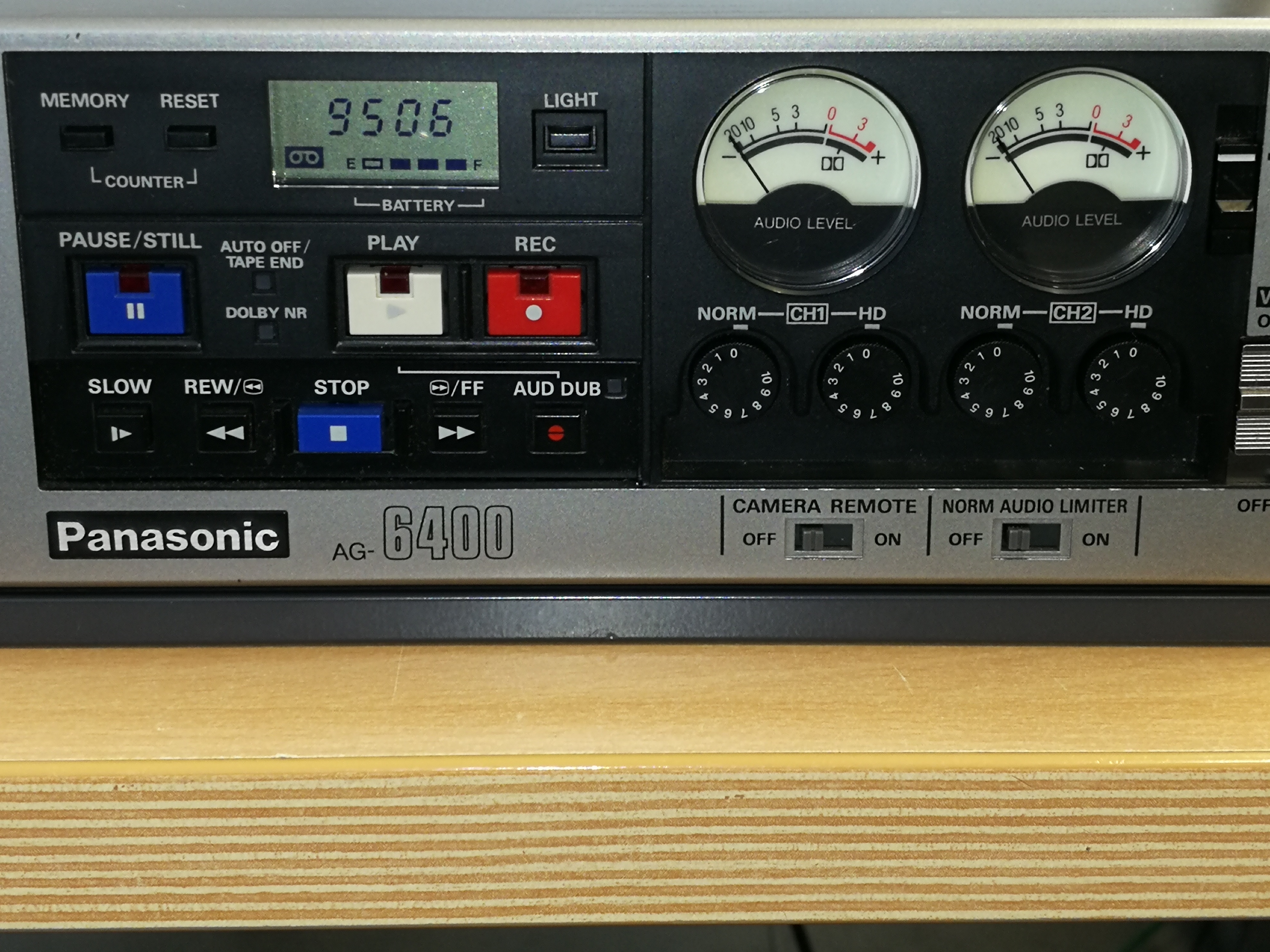
A new member of the collection of old multimedia devices is the Panasonic AG-6400. The AG-6400 is a (semi) professional video recorder from the 80s. The device records on VHS magnetic tapes and also reproduces this standard. It is portable and was the recorder for the video cameras of that time. It draws its energy from 12V NP1 batteries and can provide approx. 27W for the camera connected to it. That was about the power requirement of a 3-tube camera.
This device, too, had gotten some traces of time that largely restricted its function. Simply said – it was broken. This defect manifested itself in a stuck capstan shaft . At first I thought the shaft was ‘seized’ due to corrosion, but the reason was completely different. Interestingly, a ball bearing had been pressed out of its press fit, so that the flywheel attached to the shaft touched the bobbin of the capstan motor. The magnets in the flywheel held it in place. This error could be easily and quickly remedied by pushing back the ball bearing and then fixing it.
the videorecorder without housuingpcb folded out to service positionview to the mechanics (drumhead)
After the mechanical fault was repaired and a first function test, a fault in the 5V power supply was still to be found on the power board. This was expressed by a failure to start all drives. Here, an IC fuse was defective in the switching converter. This was triggered by a defective Schottky diode in the buck converter circuit. This bug was also quickly solved. And after checking and adjusting the operating voltages according to the setpoints in the service manual, the drive did its job again. I was even amazed at the excellent image quality that the device could reproduce. Due to its compact dimensions, I can even use the AG6400 to digitize old VHS tapes in the future.
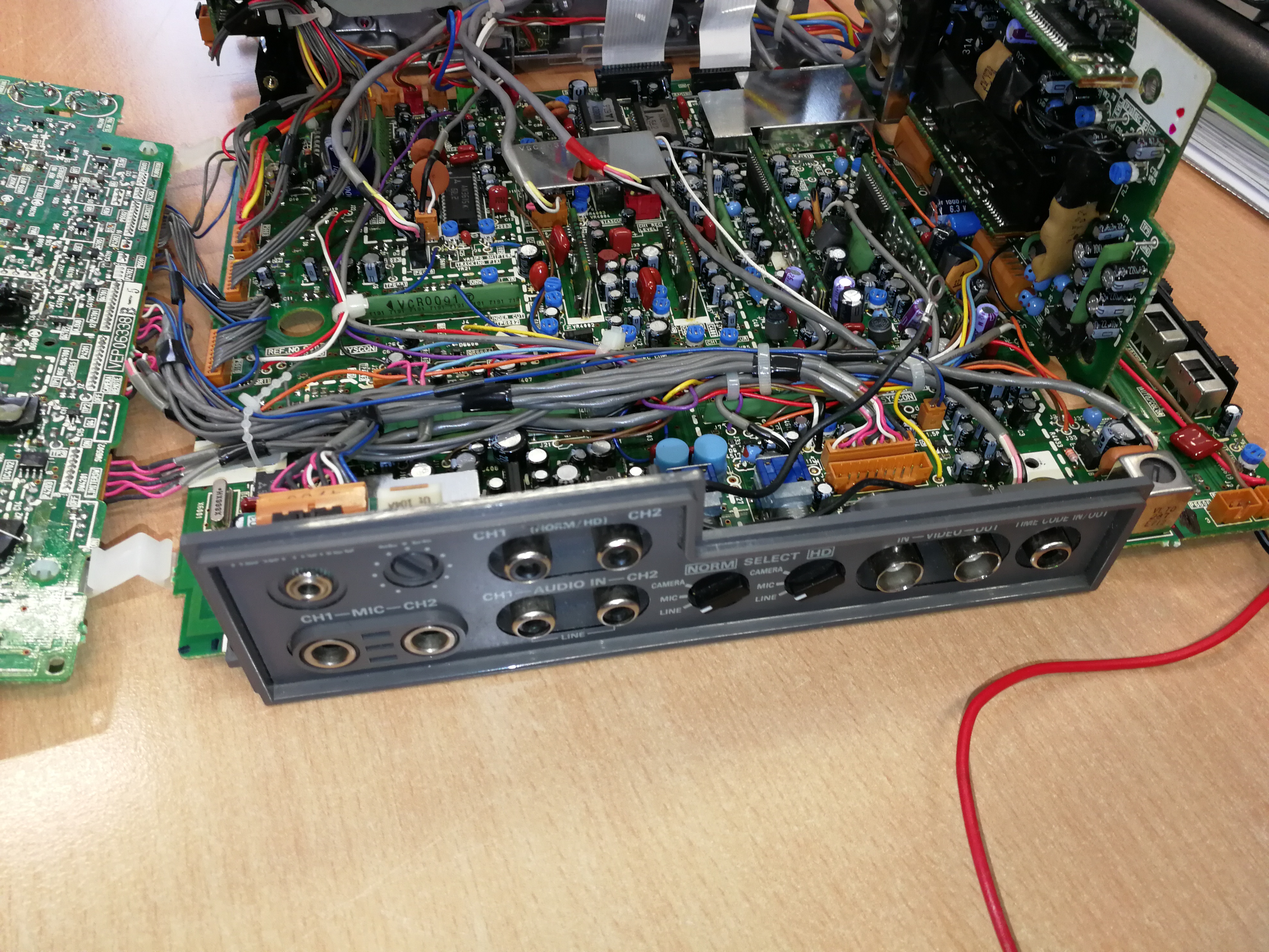
Elaborate wiring between the boards
frontview
In the data sheets and advertising for the AG-6400, the manufacturer has advertised some features and functions as follows:
High quality image reproduction
The tape speed corresponds to the VHS standard with a video track width of 49µm. Several technologies for clear and detailed image reproduction are combined in the device.
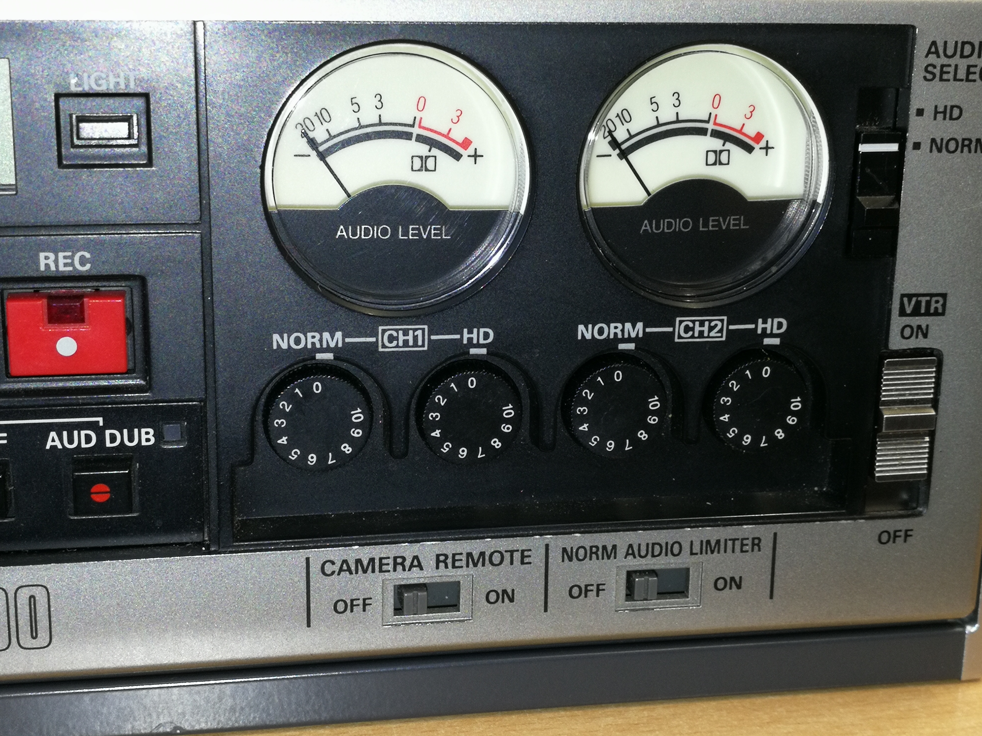
HI-FI Sound
A four-channel system consisting of two ‘normal’ audio channels with Dolby noise reduction and two ‘HD-Sound’ channels allow you to enjoy high quality recordings. A 3.5mm headphone jack and two 6.3mm microphone jacks for separate feeding of both channels, including separate control with VU meters, complete the range of audio options.
VU-meter and audio level controls
Time Code record and playback For control in linear editing systems, the recorder enables the recording of external EBU timecode signals on channel 2 of the longitudinal track.
External camersocket
A connection for an external camera with a maximum power consumption of up to 27W is also available. Cameras with 3-tube Vidicon system can be connected here.
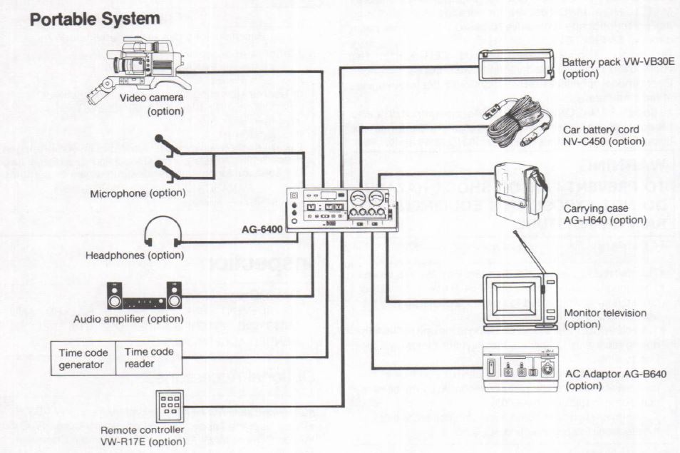
A diagram with the connection options is shown in the following picture:
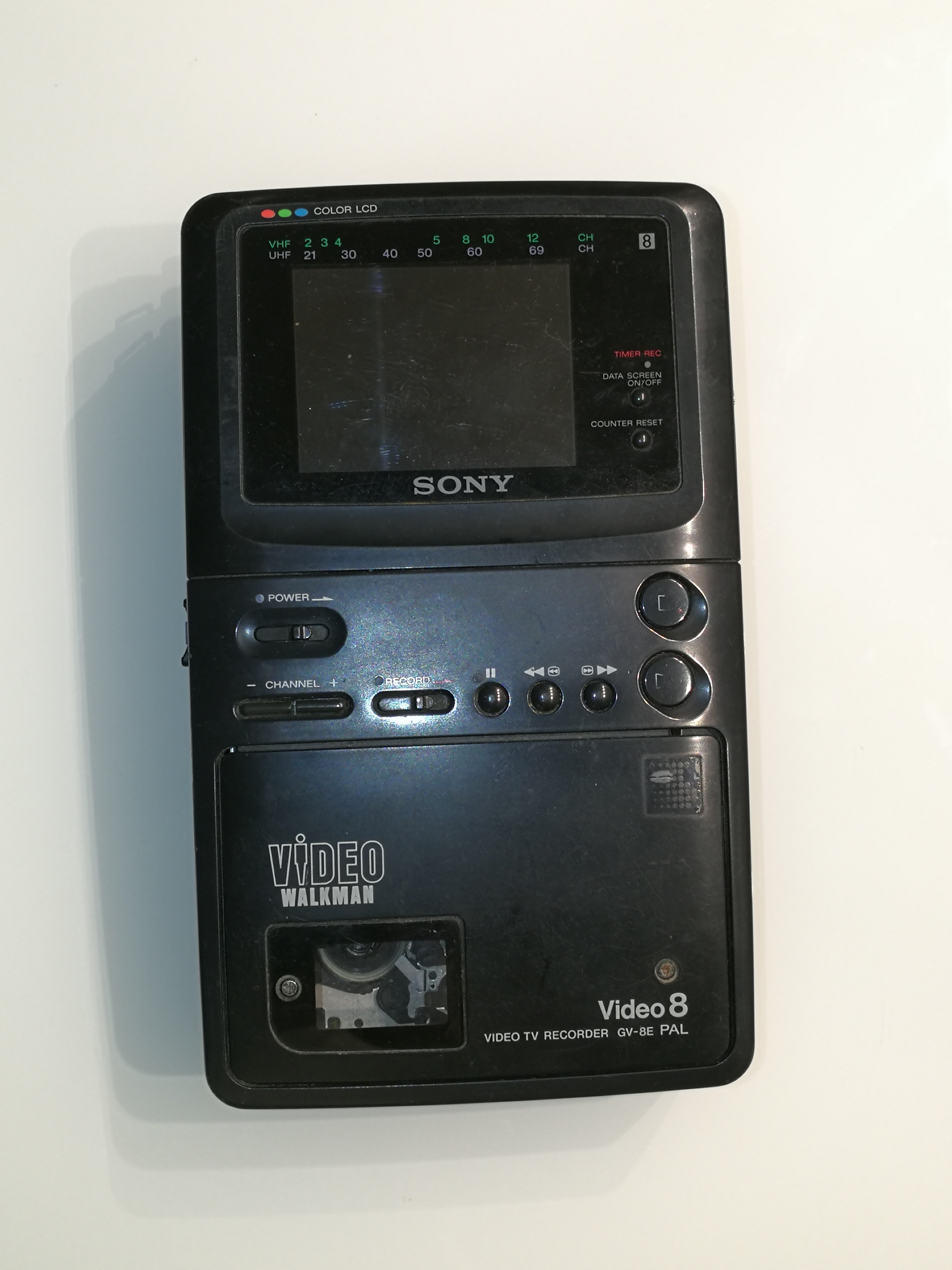
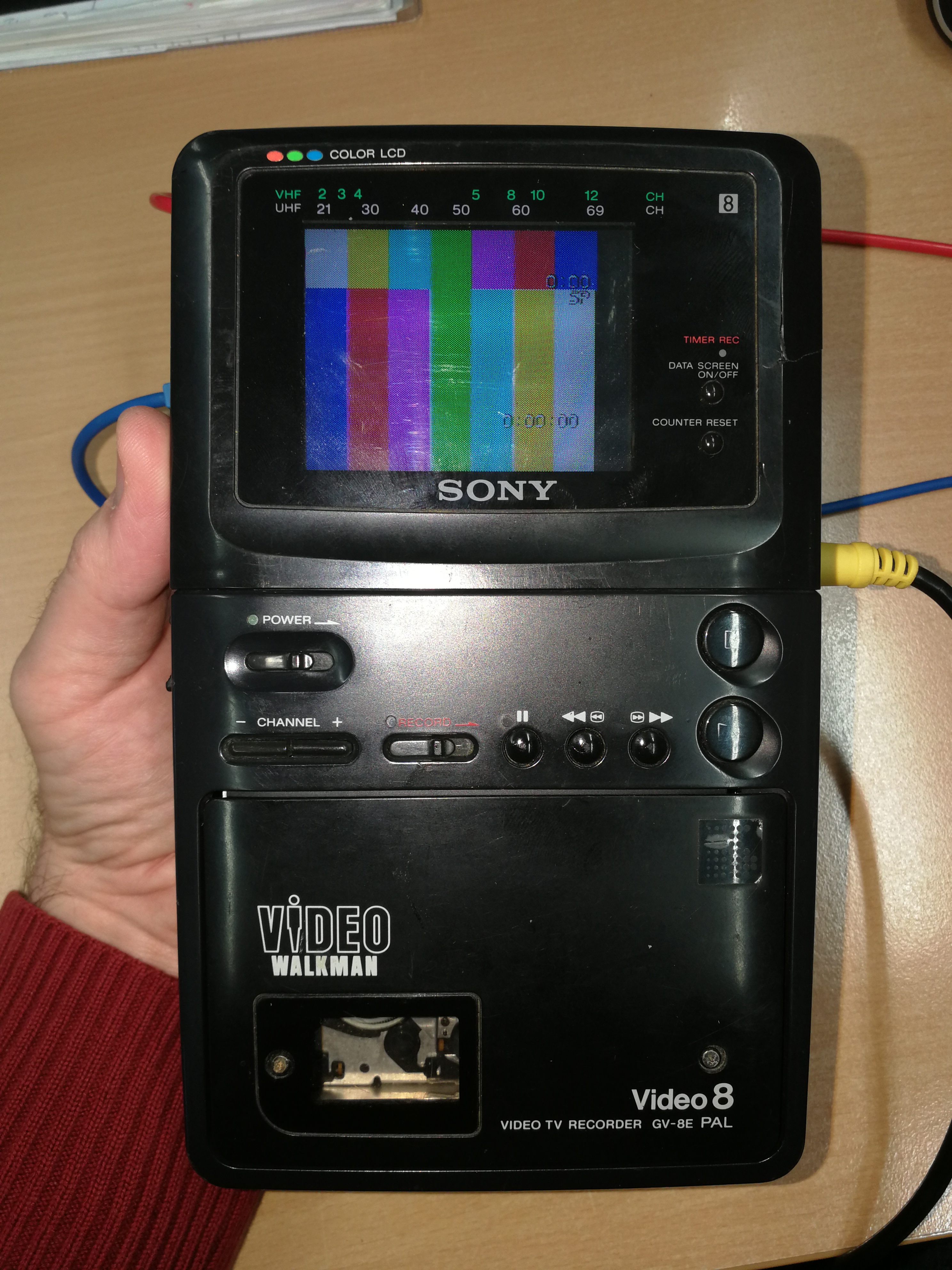
Occasionally I browse flea market websites for vintage and retro devices from the 70s, 80s and 90s. If an absolute bargain is in sight, then I strike and sacrifice a few euros. This time I found a whole box of Sony portable media players. The whole thing just cost me the equivalent of a pack of Cafe. However, the state of the devices in terms of function is also unknown. A particularly beautiful piece (yes – that’s always in the eye of the beholder) from this box is the Videowalkman GV-8E from Sony. This is a portable, analog video player / recorder that has a VHF / UHF television tuner and an LCD monitor integrated in one device. While that may not be anything exciting today, the GV8E was a very nice and expensive piece of technology when it was launched in 1988. So the portable lands on my table and gets its 6V DC supply from the power supply. The disillusionment comes as quickly as the initial euphoria. The device shows no function despite the power supply being upright. It does not react to any key press, no LED lights up. (Somehow I was expecting this or something similar)
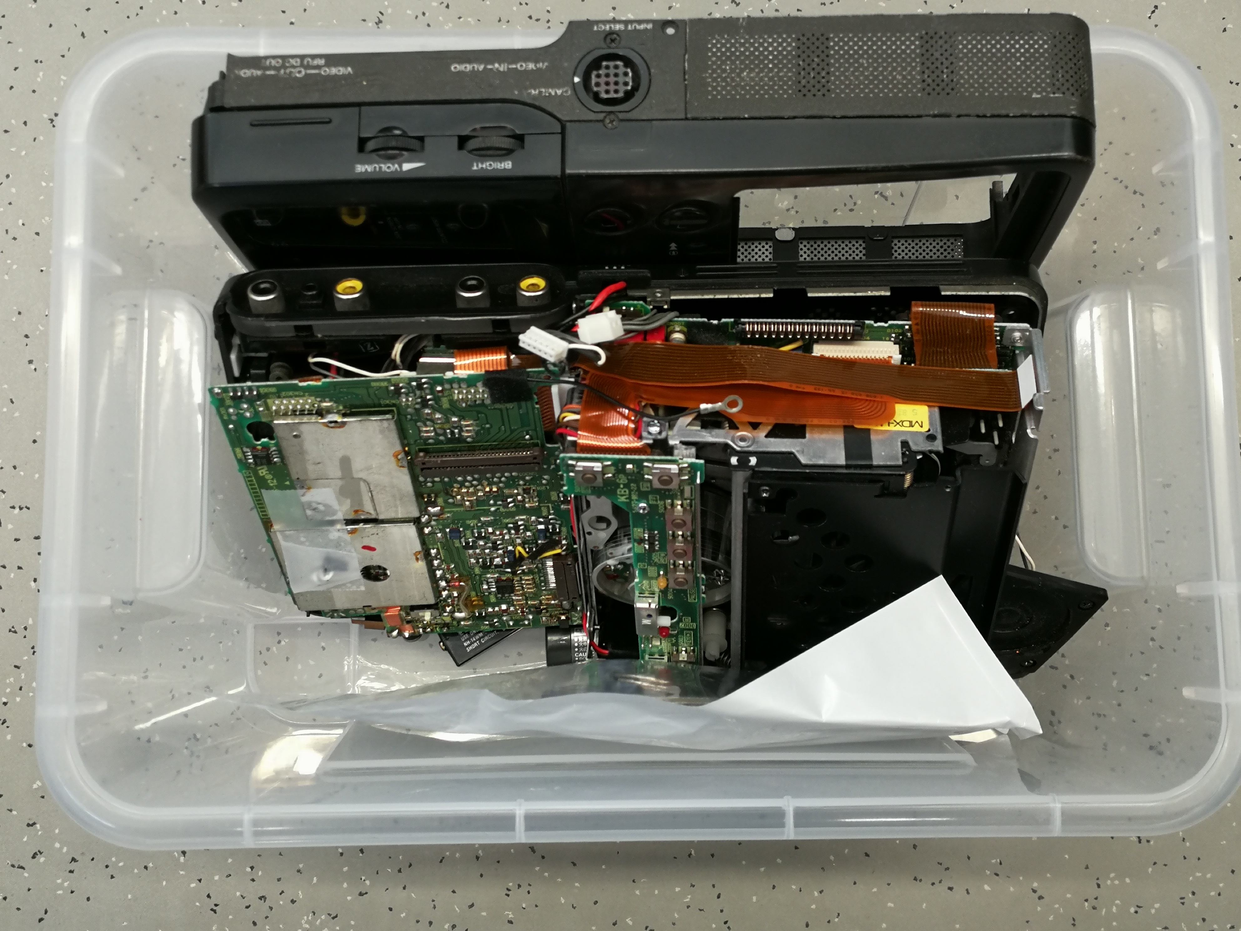
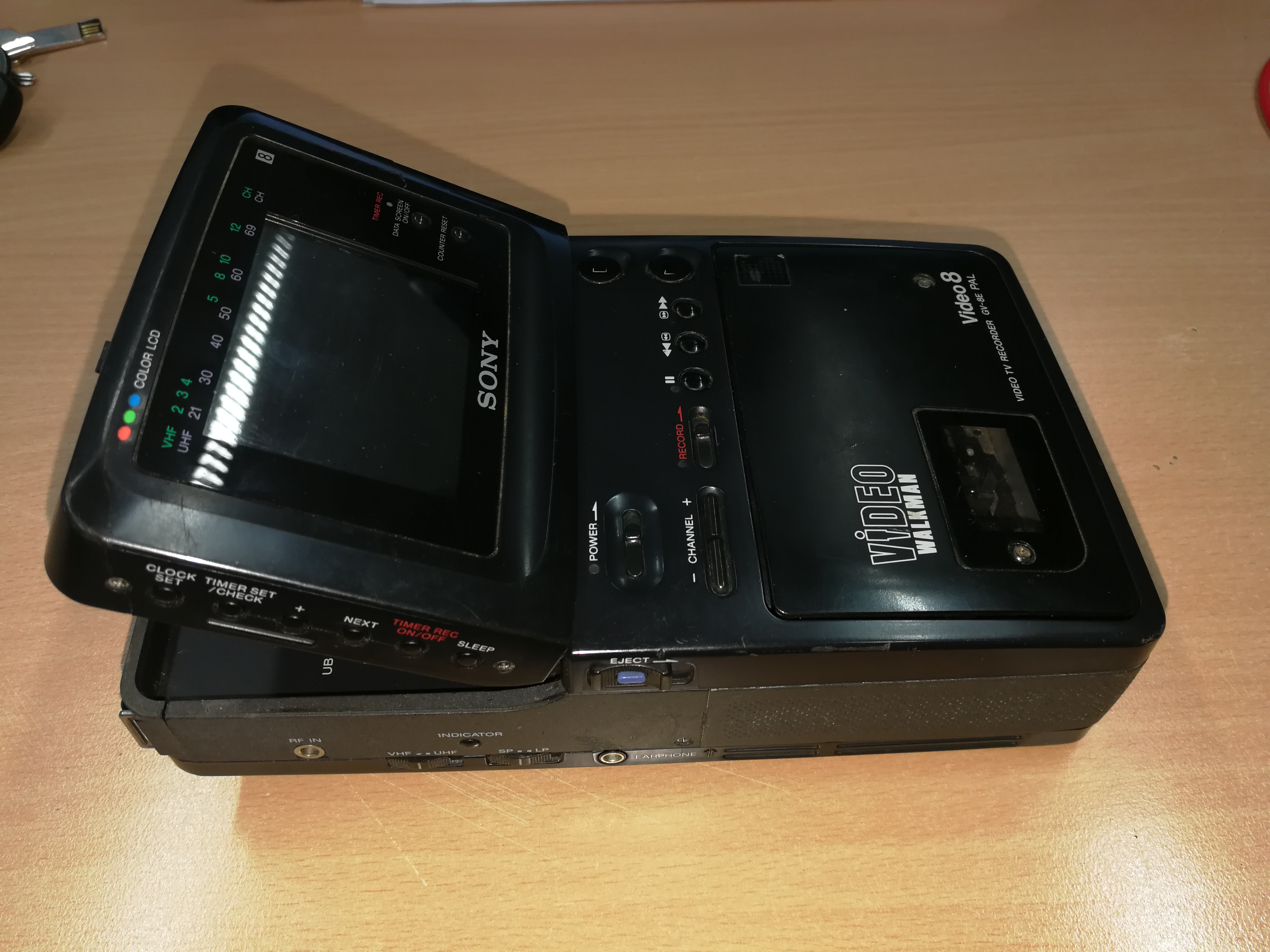
But the ambition is too great not to look inside the device and to look for the problem. I quickly started disassembling and roughly dividing the device into its components. The service documents can be found online, which are very helpful here.
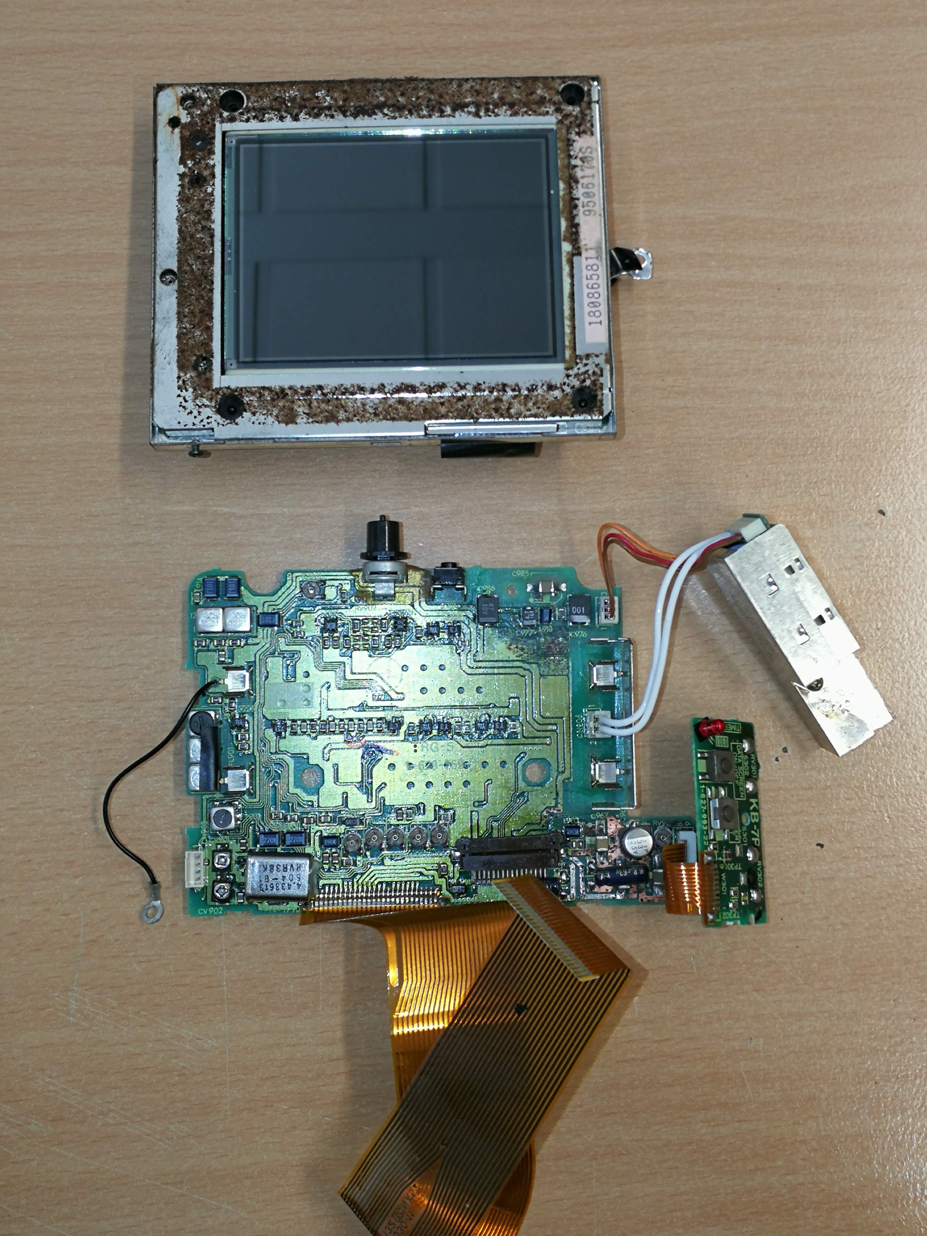
GV8E in parts
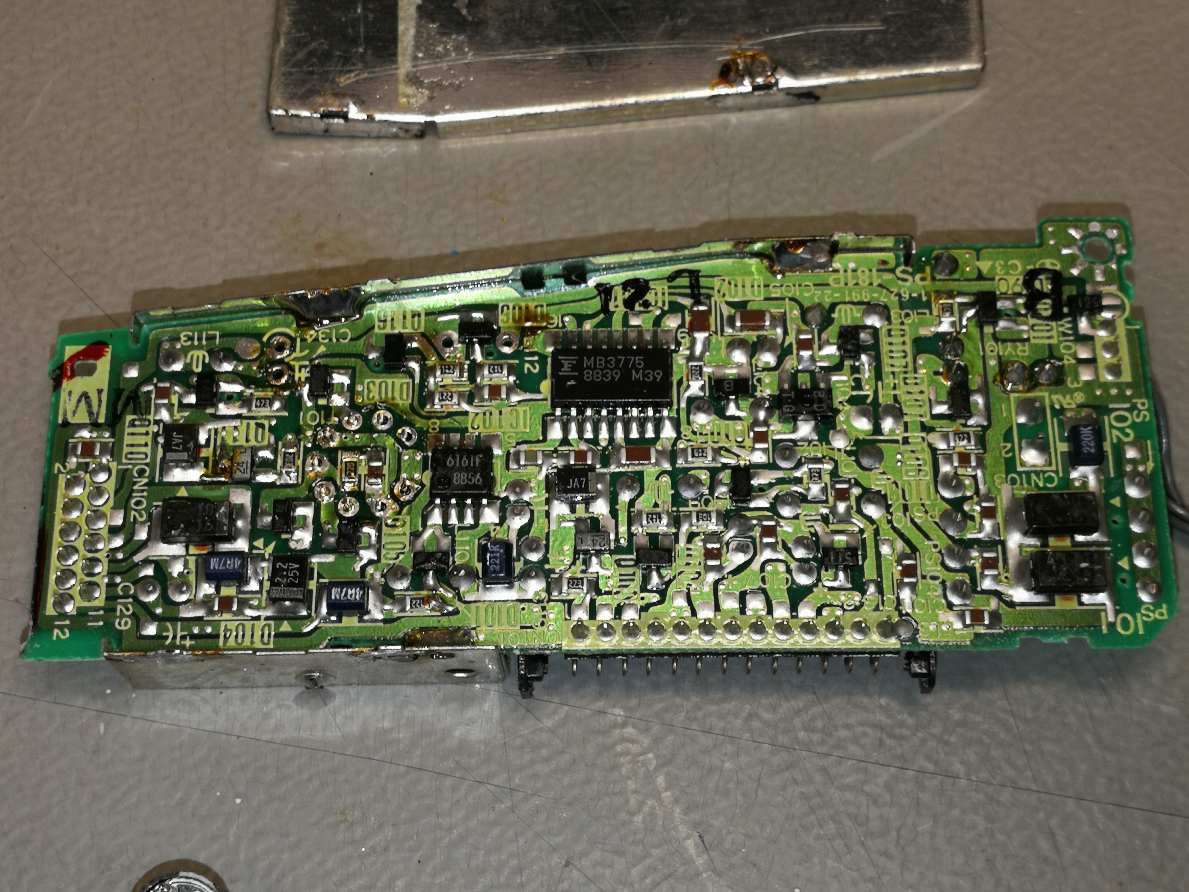
After examining the block diagram of the entire system, the start of the troubleshooting was the DC / DC converter board. This board, covered by a shield plate, produces all the voltages required for the supply of the individual components from the 6V input voltage. A measurement on the test pins on the board showed that some voltages were missing. So there must be a problem here.
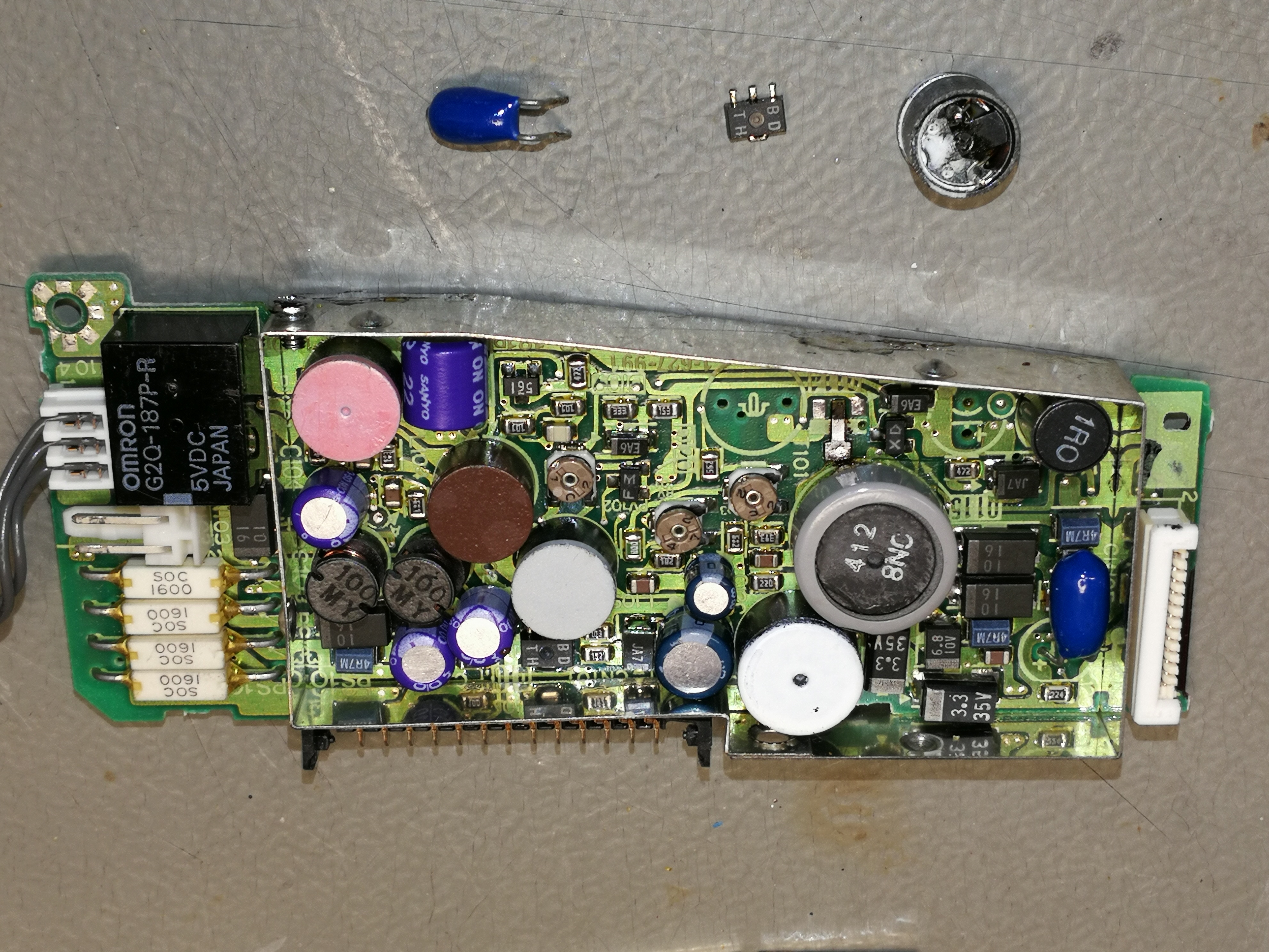
solder side of the DC/DC converter boardpartside of the DC/DC converter boards
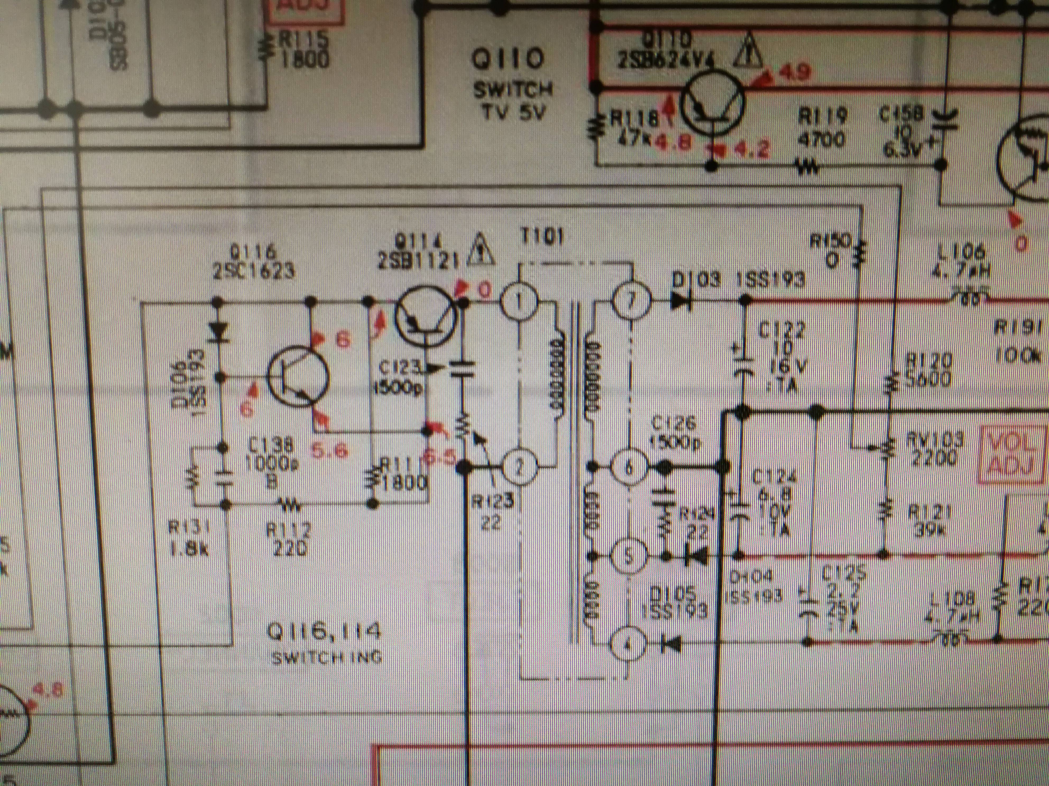
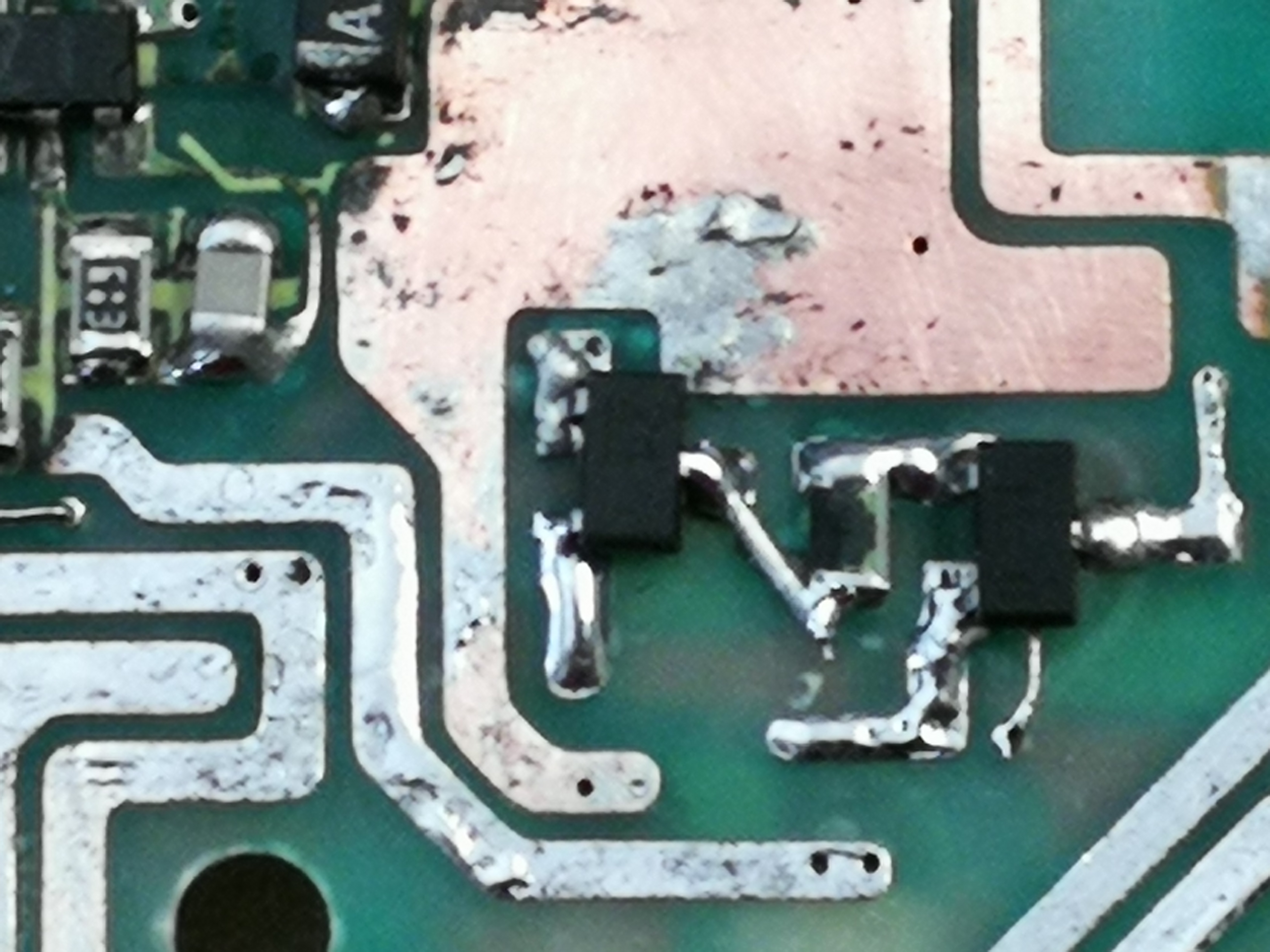
After removing the shield plate and inspecting the components, I noticed a defective 1.6A fuse (F103). This fuse protects the primary circuit of the switching converter. It can be seen from the plan that transistor Q114 was low-resistance and thus caused the fuse to trip.
extract from the circuit diagram of the DC / DC converter
The transistor is a 2SB1121 bipolar PNP transistor. Of course I didn’t have that in my collection. So thinned the component boxes for a suitable replacement …
replacement for the 2SB1121 is the PBSS5250Z
Then I found a PBSS5250Z, which has a slightly larger housing, but should do its job in the circuit.
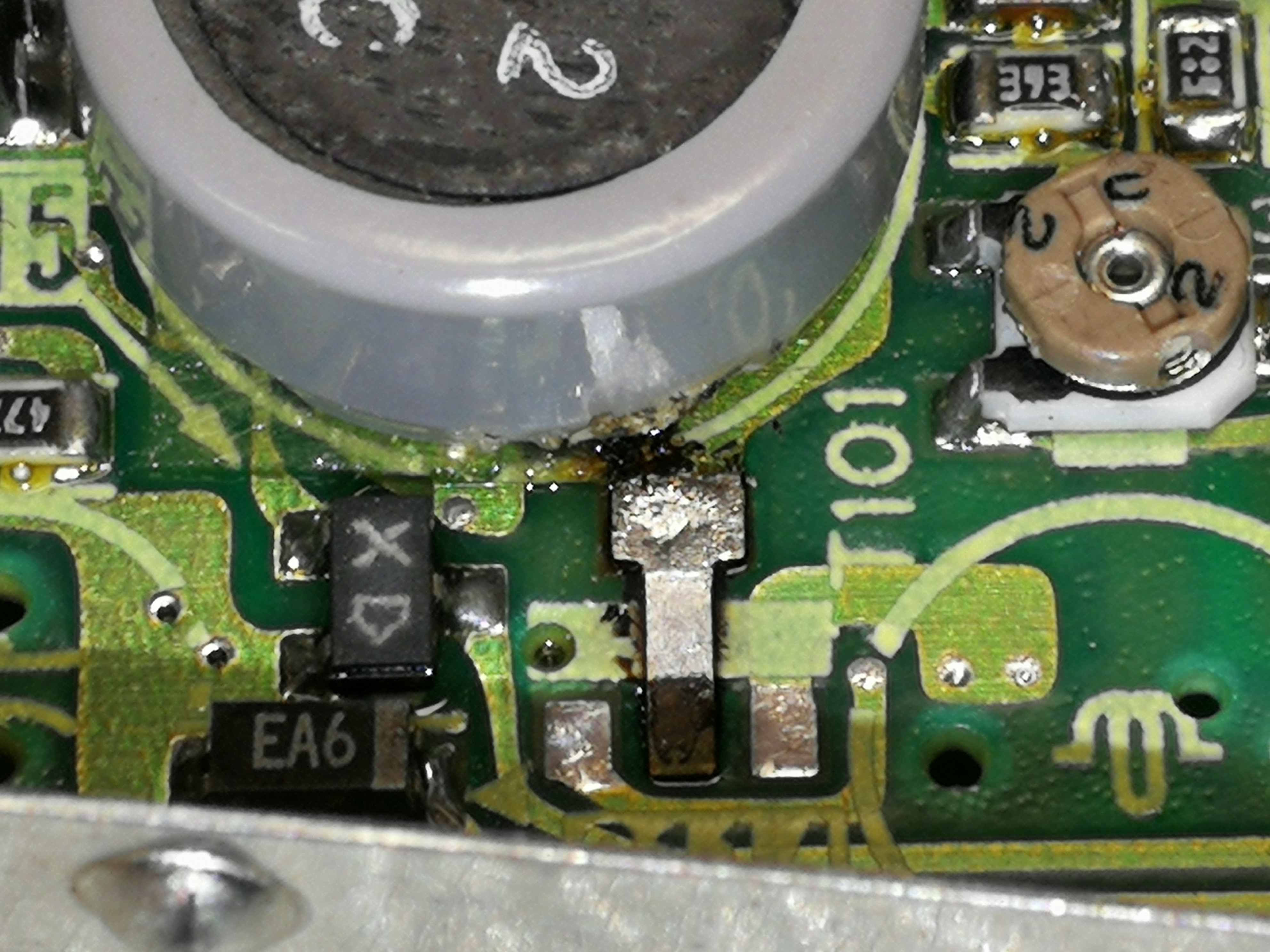
defective Q114 desodered
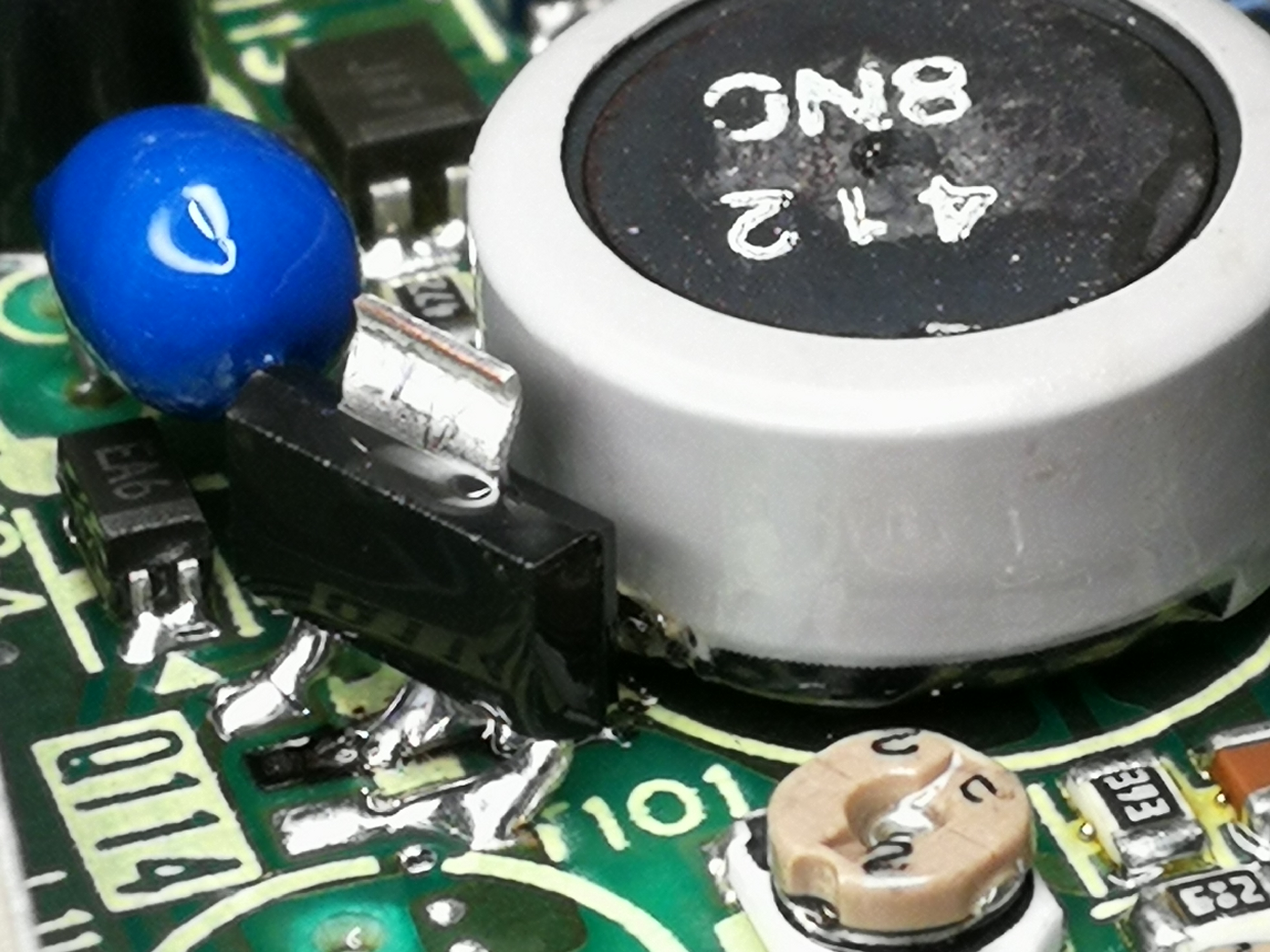
Due to the larger design and the limited space available, I could only solder the replacement transistor upright.
Q114 renewed
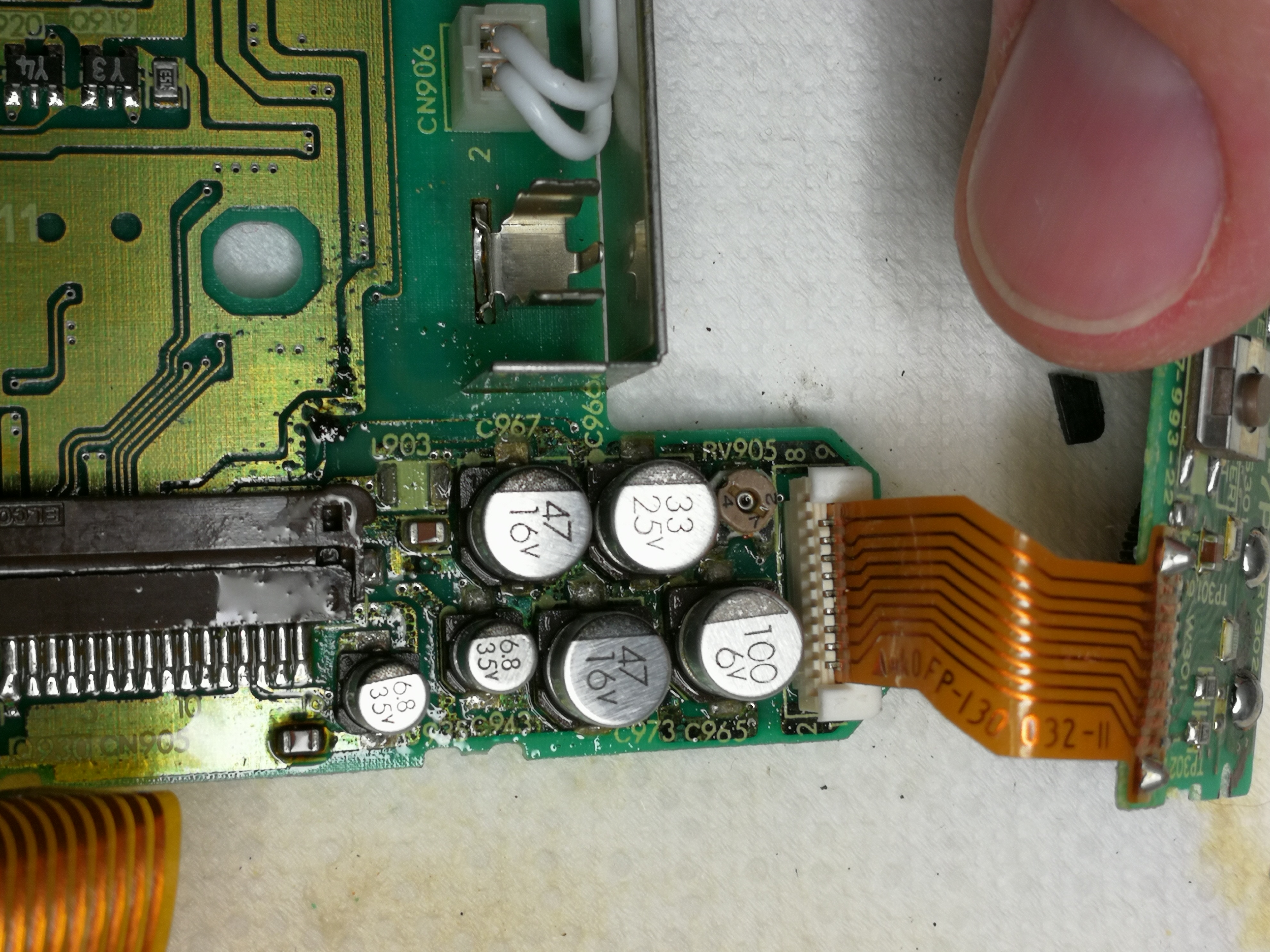
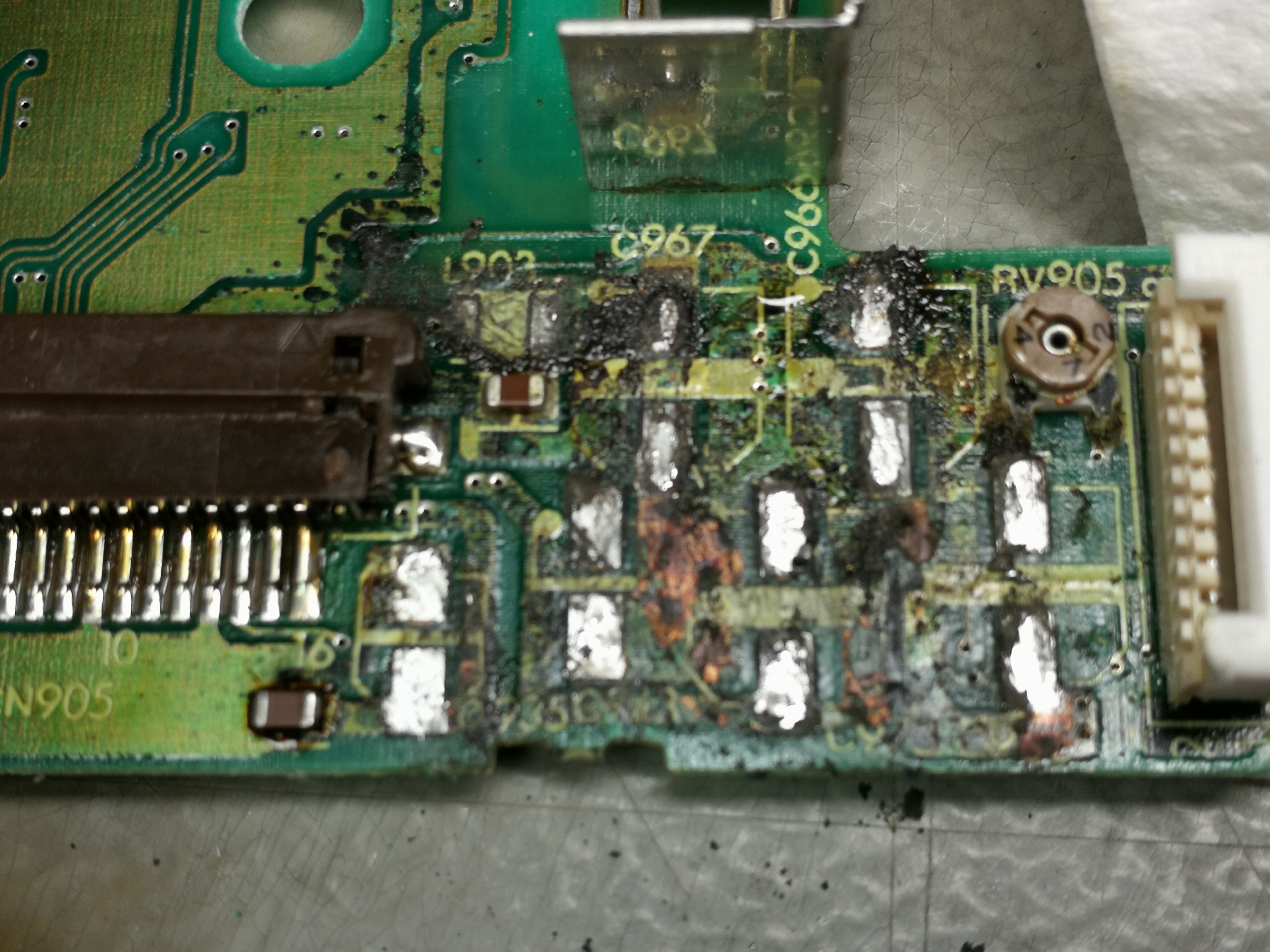
Now a new fuse is still missing in the board. After installing and checking the other components in the affected circuits, the next function test was started. All boards electrically connected again and 6V connected to the battery terminals – and look – the Powersupply board starts up and the voltages are there. Now the GV8E can be switched on again with the power button, the LED also lights up and a quiet noise can be heard from the loudspeaker. However, none of the drive motors are running and the LCD monitor remains dark. The LED lights up briefly when the “Ejekt” button is pressed, but the motor responsible for ejecting the cassette compartment does not start. That means -> continue searching for errors. First of all I will take a look at the LCD monitor. It is quickly removed and dismantled. All the less pleasing is the condition of the board. Here the “decaying” electrolytic capacitors raged with their “body fluids”. (Of course this means the electrolytes)
Leaked electrolytic capacitors
The liquid electrolytes of the electrolytic capacitors have leaked over the years and have attacked the conductor tracks and also the solder joints. Sometimes it is so bad that small components, such as SMD transistors and resistors, fall off the board as soon as they are touched. At the latest now it is absolutely necessary to have the circuit diagram of the device at hand. Otherwise it will be difficult afterwards to correctly refill the missing parts. But first the old electrolytic capacitors had to be removed.
this is what the circuit board under the electrolytic capacitors looks like
With PCB cleaner I was able to remove the remains of the electrolytes and only then could I see the damage to the circuit board. Corroded areas had to be sanded with a glass brush and burned components had to be replaced. After cleaning again, the new capacitors (this time ceramic multilayer capacitors instead of the electrolytic capacitors) have found their place.
pcb with new parts
After this procedure the time had come. The next function test started. After reconnecting all plug connections and the power supply, there were further signs of life. The backlight (CCFL) started again and in the upper left corner it was “00:00” to see the flashing clock of the on-screen display … Unfortunately, that was all. The OSD display was very blurry and the rest of the picture was white. The brightness controls did not respond. So the board had to be examined “big”.
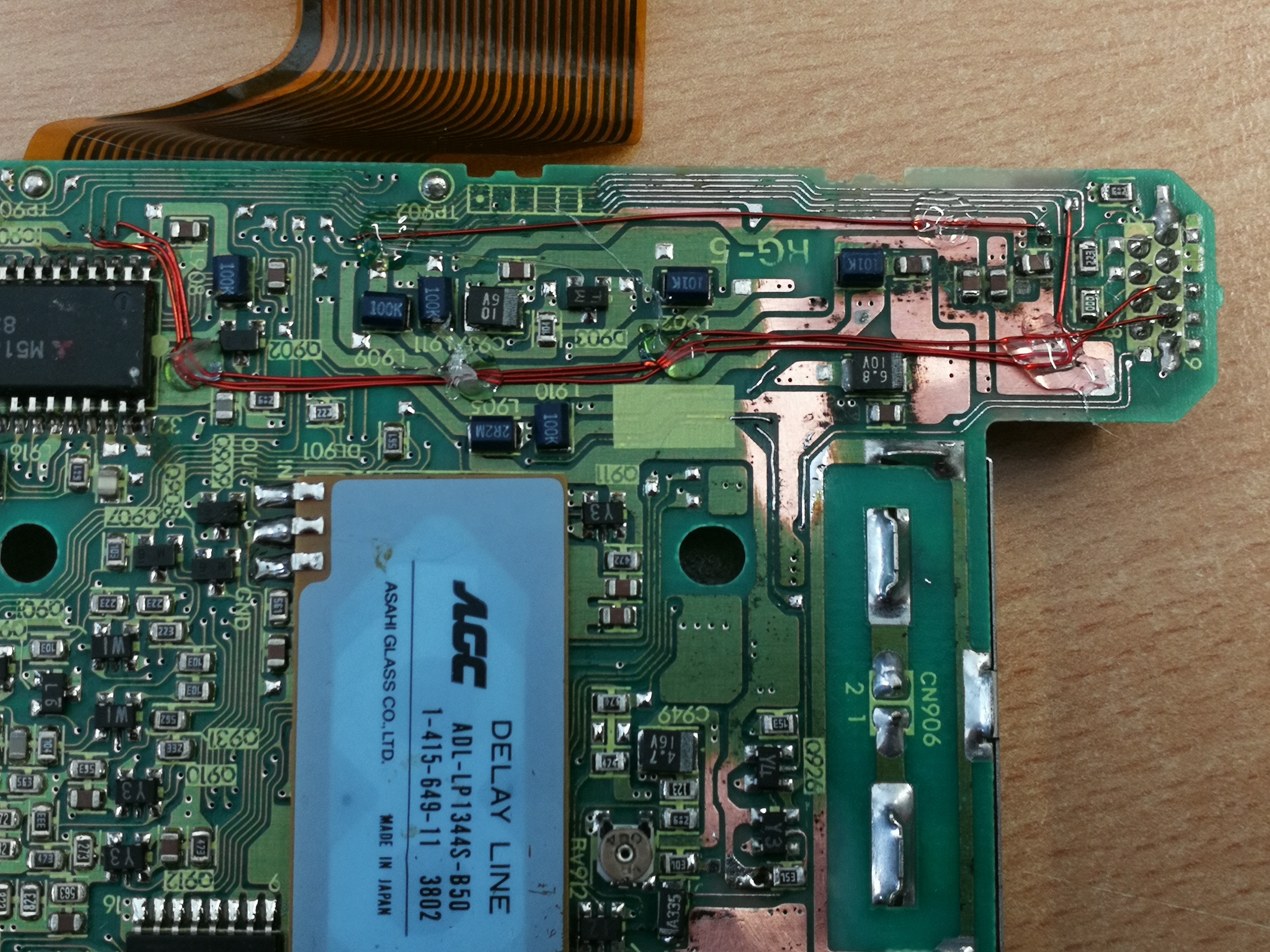
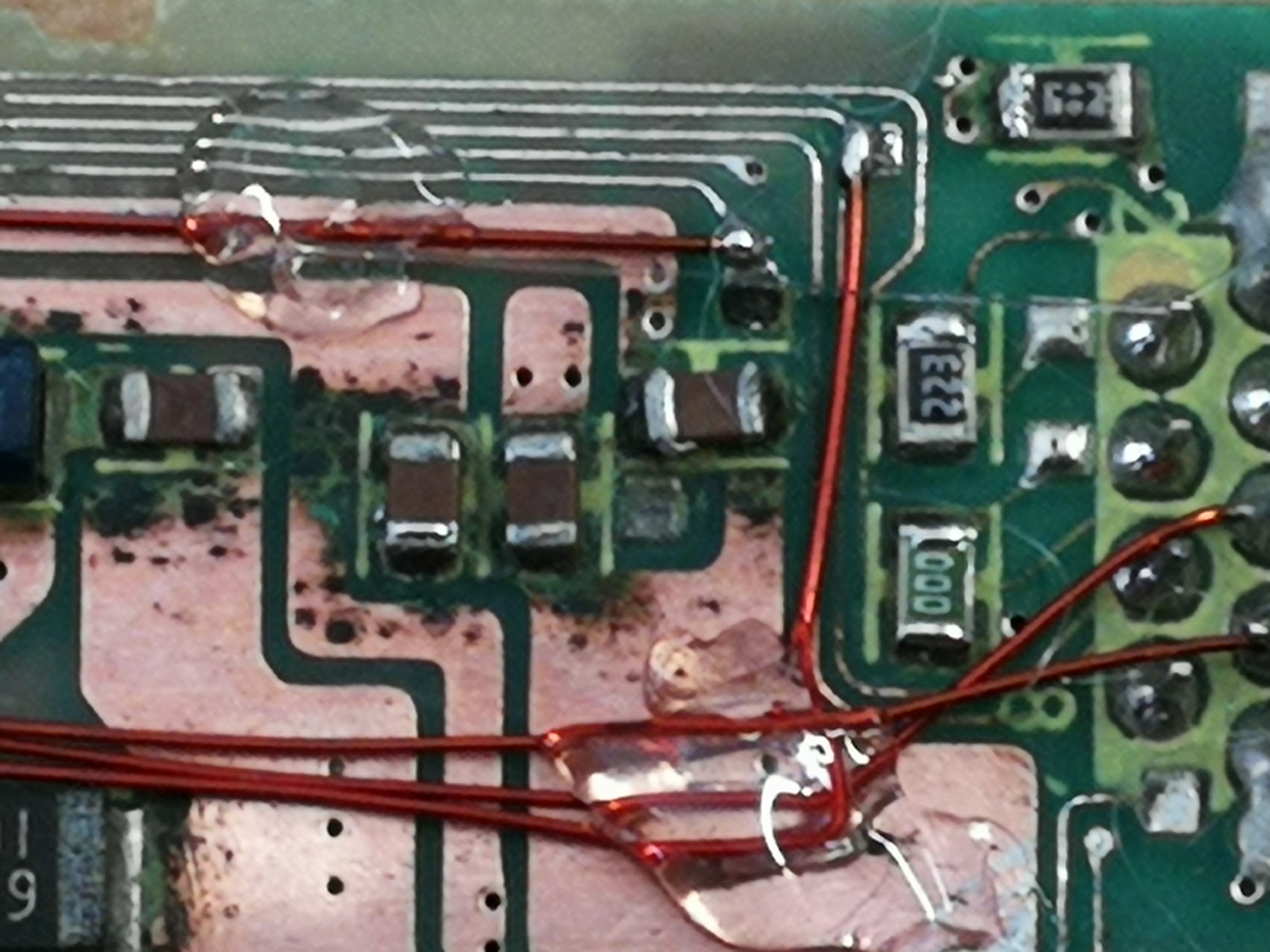
The board of the LCD monitor still had many broken conductor tracks, which had to be laboriously repaired with individual strands and enamelled copper wire. There were also some SMD components (resistors and transistors) so corroded at their connections that only an exchange helped. The result looks a bit wild, but another function test was finally positive.
fixed displayboard
After I reassembled the monitor, I went to the drive. Here, too, I first checked or renewed all SMD electrolytic capacitors, as ALL of them had really leaked out. Fortunately, the circuit boards here were not so severely etched and can be easily cleaned. Then the function test came. And unfortunately there were still problems here. There was no cassette ejection and no reaction from any of the drives. After studying the service manual and measuring many supply voltages, I was able to identify a processor as a source of errors. It is a SONY CXP80116.
Sony CXP80116
This chip controls all drives, leds, queries sensors, etc. It is also responsible for ejecting the cassette compartment. It controls a driver IC (bridge) via pins 20 and 21, which in turn supplies the charging motor. And exactly the two outputs remained at 0V. When the “Eject” button was pressed, only a few millivolts were measured instead of the 5V. So at first there was a suspicion that the driver IC has an error and is pulling down the outputs of the controller. So the outputs from the controller to the motor driver were separated and 5V directly connected to the motor driver input – and lo and behold, the loading motor was activated. So the problem is with the 80116. After some back and forth I was able to find one of these and exchanged it. Another test pleased me, because the cassette could be loaded again and the head drum started.
And the next problem already appeared. One of the two loading arms only drove half off and then got stuck. That means I also have to disassemble the mechanics of the drive. Said and done. Fortunately, it was only a small bolt that holds a drive lever. This had loosened and slipped out. So the problem was quickly resolved. Now I was finally able to do a function test again. And this time everything worked. The cassette was loaded, the head disk started, the tape was threaded and finally it could be played. After I had tested all functions, the GV-8E can be reassembled. Now he can go to the showcase as a “museum piece”;)
working again
Technical data of the GV-8E:
Video recording System: Rotierendes Zweikopf-Helical-Scan-FM System
Audio recording System: Rotierender Kopf, FM System