Tag Archives: radio receiver in retrolook

Radioreceiver in retro look – The finishing

Loading

IMAG1299
The wooden case is painted

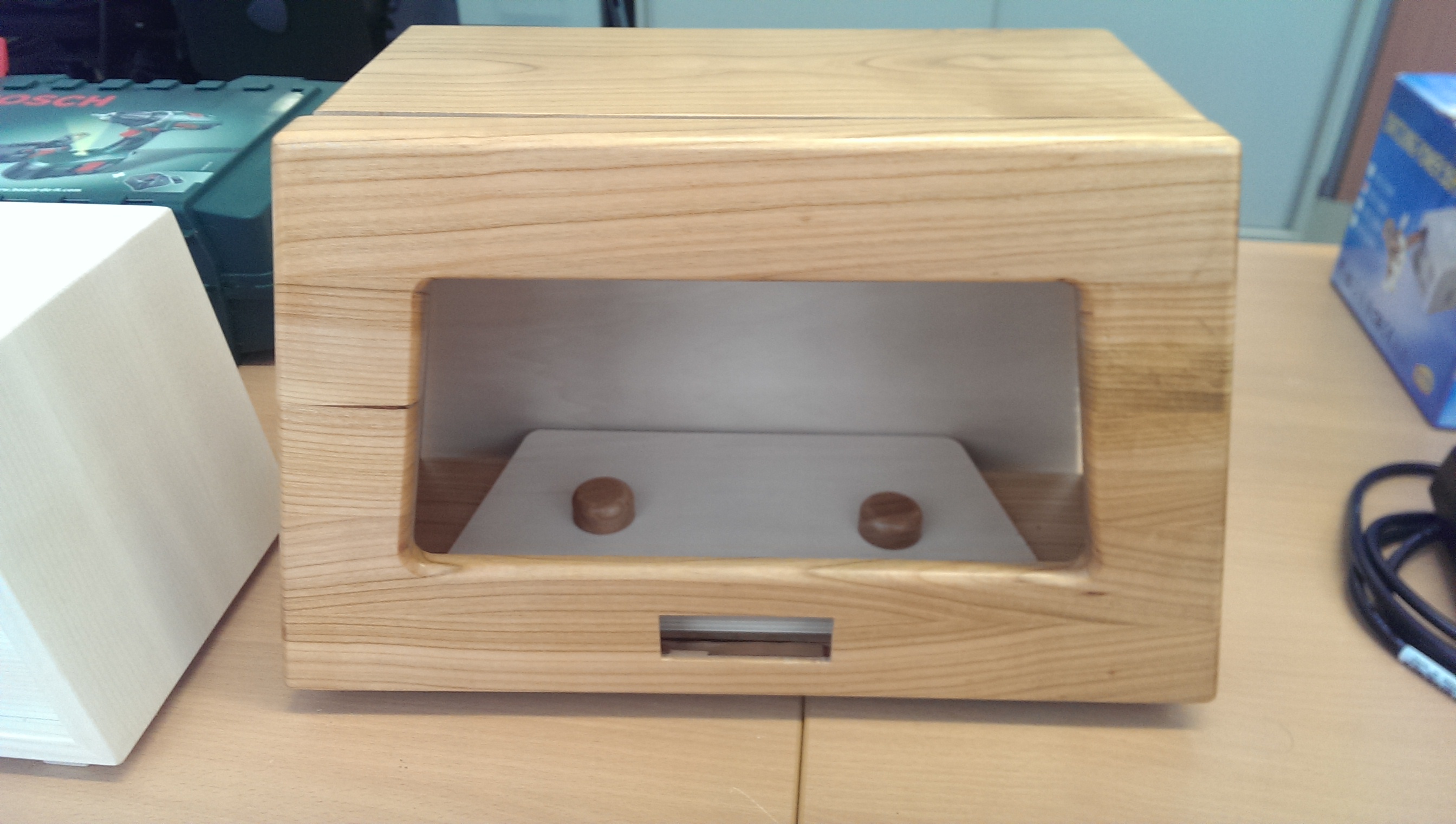
Now that the front panel is milled, it can be cleaned and the engravings are provided with black paint. After the varnish has dried in the indentations of the engraving, the supernatant paint is removed with solvent. Now the entire panel could be painted with clear lacquer.

While the paintwork on the front panel is drying, it’s time again for the wooden cabinet. The mounting holes for the boards, speakers, etc. were drilled and then the wood was embedded with a slightly darker wood stain. After drying, the wooden case also gets a clear coat.

In the next step, the operating elements (switches and rotary encoders) and the LC display are attached to the front panel. The milled webs for the speaker panel are covered with black fabric. (For the fabric had to serve a T-shirt).

IMAG1307


The painting of the housing dried about a day. Now you can start mounting the speakers and the board.

IMAG1301
Installation of the speakers


Die Platine wird mit Abstandhaltern am Gehäuseboden verschraubt.

IMAG1302
Assembly of the board


Now a suitable power supply is missing. For this purpose, a small power supply was built, which consists only of an iron core transformer with subsequent rectification, smoothing and voltage stabilization with a LM7809, ie 9V DC. For this, a small board was made (about 5x8cm) and also built into the housing with spacers.

IMAG1328
Power supply 240V AC to 9V DC at max. 350mA


Now that everything is assembled, the amplifier metrics and levels are again set and optimized with signal generator and oscilloscope.

IMAG1332
Adjustments


The finished radio receiver now looks like this from the front …

IMAG1308
Radio from the front


und die Geräterückseite ist im nächsten Bild dargestellt:

IMAG1333
back

In the short video, the radio can be seen in operation:

Radioreceiver in a retro look – Update: The case

Loading

IMG-20150130-WA0000-2 It’s time! The first picture of the absolutely real wooden housing for radio electronics is here. A beautifully crafted housing made of glued elements. This work comes from Gebhard’s hands, a master carpenter from the Upper Carinthian region;)

IMAG1272
Housing with holes for the speakers

Jetzt kann das Nostalgie-Radioprojekt wieder einen Riesenschritt nach vorne machen.

frontpanel
This will be the aluminum front panel

The case is on our table. First, the holes for the speakers were drilled. Later these should be covered by a milled aluminum panel. So the next step is to construct the milling data for the front panel. Here again the layout tool “Eagle” is used. The data can simply be exported as a “.dxf” file and imported into the circuit board plotter software.


UPDATE:

Barely a few minutes, I went to the circuit board plotter, imported the production data, clamped the “two-cutter cutter”, of course, the aluminum blank and off we went.

The speed for the 1mm cutter I have chosen with 60000 rpm and set the feed rate to 1.5mm / s in both axes. Cooled and lubricated was the way with alcohol.

A not negligible amount of work is, by the way, the cleaning of the plant after the work done … 🙂

IMAG1281


Radio in retro-look – KnowHow for the apprentice – Part 2

Loading

… to realize the volume control via the microcontroller, a “digital potentiometer” X9C102 was simply used. It is controlled directly by the controller with a “direction input Up / Down” and a “count input”. Internally, this IC consists of 100 resistors connected in series whose “tap” is determined by counting input. So a simple matter to control the signal level of the preamplifier in 100 steps ….


Continued from Radio Part 1
The controller should now be operated via a push / turn wheel (rotary encoder with push button). In order to be able to evaluate the direction of rotation of rotary encoders, a second pulse output is required. The two pulse outputs must be shifted in their sequence depending on the direction of rotation (phase shift). In order to convert the pulse sequence into a direction signal and a clock signal, we have set up a small decoder logic using a JK flip-flop and a Schmitt trigger / inverter …

Turnwheeldecoder

The outputs of the decoder logic are now passed directly to three microcontroller inputs. Thus, now a suitable program can be created, which provides a simple menu-driven user interface. The parameters are displayed on a two-line LC display. The outputs of the controller, in turn, control the “digital potentiometers” for the volume setting and, of course, the I²C bus, which sends the commands to the FM module. An additional output allows the switching of a relay, with which, for example, the audio input from the amplifier can be switched between the FM module and an external signal source. The LC display is connected to the controller in 4-bit mode and the backlight of the display is also switched by the controller.

 
PCB fresh from production

After all these functionalities had been defined, we were going to transfer this information to the Layout Tool or the schematic.
Finally, a layout was drawn and made. Subsequently, we could start with the assembly of the board and then carry out the first commissioning. After the adjustment of the amplifier quiescent currents, the development of the Arduino code began. Here, the work is extremely facilitated, since there are many finished libraries here, which can be used directly for its purposes. For example, the only challenge with getting an LC display up and running is to connect the few wires to the uC (microcontroller) and pinpoint the pins in the code. Everything else is done by the library. With this simplification, the functions are then implemented quickly and the first test run can begin.

ready assembled PCB

As a result, the software will be even better – perhaps saving multiple stations, and so on. But the next step will be to build the board into an enclosure modeled on the old radio tube radio receivers. It should be made of solid wood. The operating and display elements are to be installed in an aluminum plate placed on the front of the housing … (Another post on this blog will follow.)

The first functional test can be seen in the video below …


Radio in retro-look – KnowHow for the apprentice – Part 1

Loading

THE IDEA FOR THE PROJECT
A project idea that came to my mind as an ideal apprentice project is to plan and build a radio receiver. With this project, our apprentice should apply the acquired skills in a practical way and set up an FM radio receiver according to the components to be used.
This was done gradually. I came up with the concept in the following parts:

THE AMPLIFIER
First, a simple class A audio amplifier should be built. The apprentice should build the amplifier according to the circuit on the breadboard, metrologically examine and understand above all. In the next step, the Class A amplifier became a Class-AB amplifier. Again, the task of the apprentice was to understand the operation and optimize the breadboard function pattern so that a (not metrologically) at least reasonably “good” acoustic result was achieved.

First functional pattern of the “power output stage”

When this succeeded after some time, he got the task to transfer the determined circuit into a layout tool and expand it to a second channel, while also creating a power supply concept. The power supply should not only supply the amplifier output stage, but also for other components (such as microcontrollers, USB interfaces and what ever came to mind) a + 5V and + 3.3V DC supply available.
After many layout designs, he then presented me with a layout in which the components were symmetrical and technically reasonable (Trimmpotis should be accessible …) were arranged. So he was allowed to make the layout as a functional sample. (etch the board, populate it and try to get it all working).

The learning effect was gigantic: D, because in the implementation of theoretical circuits to a simple breadboard construction and then to the “printed” circuit on the print, there is a lot of sources of error. And they also want to be found and corrected. Our trainee was able to practice patience and precise work.
But in the end, the 440Hz sinewave of the frequency synthesizer sounded from both connected speakers …

Now it was time to think about the signal source, the actual receiver.

THE FM RECEIVER

FM-Receivermodul

In a Chinese online shipping I discovered an FM receiver module with a very compact design (a print with about 12x12mm) on which a complete receiver is integrated. The module is called TEA5767 and uses the eponymous Philips FM receiver chip.
The connections to the module consist of power supply, audio L and R outputs, as well as an I²C bus to control or set the reception frequencies and an antenna and Muteeingang. So ideal to realize a signal source for our amplifier. But that raised further questions.
How should one generate the control signals for the I²C bus, how should the tuning of the transmitters be done, how should the device be operated by the user at all? For all these questions, there is a simple answer: Take a microcontroller. And as the apprentice likes experimenting with the Arduino UNO board, I decided to use an Atmega328, the Arduino UNO controller.

THE HEART OF THE RADIO – THE CONTROLLER

The microcontroller should therefore take over the complete management of the radio, thus fulfilling the following functions:

  • set the stations (generate I²C commands and send them to the radio module)
  • save the tuned stations (in the internal EEPROM of the controller)
  • show all information on a LC display
    take over the volume control
  • generate operation by means of a push / turn wheel (incremental encoder with touch function should take over the entire operation of the radio)
 Folie1
blockschematic

So we had to extend the circuit by a few components. The audio output of the FM module had to be pre-amplified. This was done by a small AudioOPAmp. To realize the volume control via the microcontroller, simply a “digital potentiometer” X9C102 was used. It is controlled directly by the controller with a “direction input Up / Down” and a “count input”. Internally, this IC consists of 100 resistors connected in series, whose “tap” is determined by counting input. So a simple matter to control the signal level of the preamplifier in 100 steps.

continue in the next part