![]()
II am always fascinated by the topic of radioactivity. More precisely, it is the measurement or detection of this ionizing radiation, which is produced by the decay and of atomic nuclei with the release of energy. A basic distinction is made between the energy (alpha and beta particles) emitted by the movement of the decaying particles (i.e. particle radiation) and the radiation energy that is transported as an electromagnetic wave (gamma radiation and also X-rays). These types of radiation have different energy densities and ranges. Depending on the type, they are more or less easy to shield. Alpha radiation is particle radiation that is strongly slowed down by matter (air, water) and no longer penetrates a sheet of paper. However, these particles give off the energy over their very short distance. This is particularly dangerous if these particles are inhaled or radiate on the upper layers of the skin. Gamma radiation in turn penetrates matter very easily like a radio wave and can be shielded most effectively with lead. It goes without saying that this type of radiation is anything but harmless.
You cannot see, smell, taste or otherwise perceive this radiation directly, but the danger is still there. With relatively simple techniques, however, these decay processes can be made visible or audible and counted.
This has been done for a long time with a so-called counter tube or, thanks to modern technology, with semiconductors. A P-N junction is operated in reverse direction and the very small reverse current is measured with the exclusion of light (i.e. darkened). If high-energy radiation hits this P-N transition, the current flow is increased for a short time and can be detected.
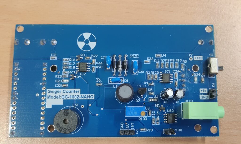
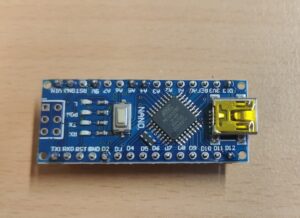
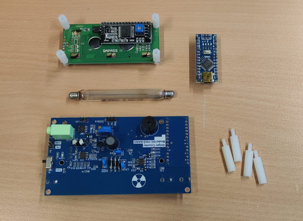
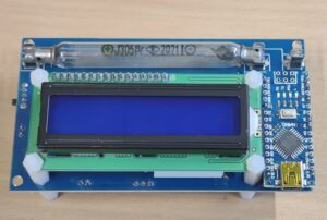
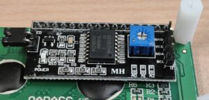
Whenever the opportunity arises to get a detector very cheaply, I of course take it. So this time too. I had to look at a simple kit based on detection using a counter tube. The kit comes from the Far East and consists of a base board, an attached Arduino Nano and an LC display that is also attached.
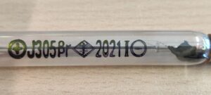
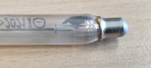
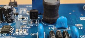
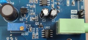
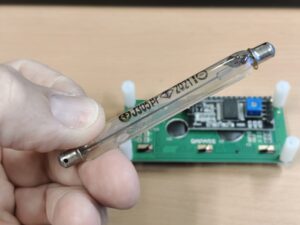
All components required for detection are on the mainboard. This includes, among other things, the generation of high voltage for the counter tube, which is implemented using a simple boost converter circuit driven by a 555. To attach the counter tube to the mainboard, the designer of this board chose simple glass tube fuse holders. They don’t fit exactly, but they can be stretched so that they hold the counter tube firmly in place. Incidentally, the counter tube is a J305. It is approx. 90mm long and has a diameter of almost one centimeter.
The counter tube works with an anode voltage of 350V to 480V. Below I have listed the specifications from the data sheet:
- Anode voltage: 350 v bis 480 V
- Type: J305 Geiger-counter tube
- Cathode material: tin oxide
- Wall density: 50 ± 10 cg/cm²
- Operating temperature range: -40 °C bis 50 °C
- Diameter: 10 mm (±0,5 mm)
- Length: 90 mm (±2 mm)
- Self-background radiation: 0,2 pulses/s
- Sensivity to γ-radiation: 0,1 MeV
- Current consumption: 0,015 mA bis 0,02 mA
- Working voltage: 380 V bis 450 V
- γ-radiation: 20mR/h ~ 120mR/h
- β-radiation: 100 ~ 1800 Pulse/min.
- 100 ~ 1800 pulses/min.
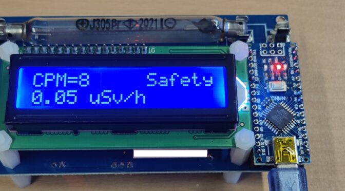
The signal detection and processing of the signal also takes place on the mainboard. The recognized impulses are reproduced via a small piezo loudspeaker. In order to be able to count them, you don’t have to sit in front of the loudspeaker with a stopwatch and count the beeps every minute – no – that is done by a microcontroller, which, as is common today, consists of a finished board. Here the designer has chosen an Arduino Nano (or nano replica). In turn, a program runs on it that counts the impulses and also shows them nicely on a two-line LC display and ideally also converts them into µSievert / h. To transfer the pulses to the Arduino, the level of the signal is brought to TTL level and switched to the interrupt input of the Arduino. The LC display uses the I2C output of the Arduino. The lines for this are only led from the socket strip into which the Arduino is plugged via the mainboard to the socket strip for the display. To supply the whole system with voltage, the 5V from the USB port of the Arduino are used directly. Optionally, the 5V can also be connected to the mainboard via a connector strip.
Once everything has been assembled and the USB supply is connected, there is first of all a short waiting time during which the high voltage is built up. Here the programmer has come up with an animation that shows “Boot …” on the display.
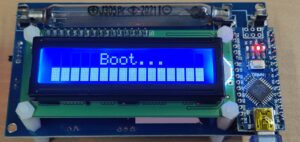 And then it starts. The Geiger counter is ready for use and begins to count. As a test I only have an old clock with hands painted with radium paint. There is at least a clear change in the number of detected counting pulses when the watch is brought near the counter tube.