Tag Archives: Photovoltaik

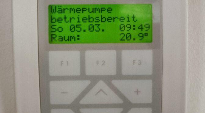
Integrating the heat pump (NEURA) into the Smarthome

Loading

A smarthome is no longer a rarity today and is very widespread. There are countless systems on the market that make your own home “smart”. The digital voice assistants from Google, Amazon and co. in conjunction with smart light bulbs are among the systems that are easy and quick to install. But there are also complex smart home systems, in which actuators for every lamp and socket are installed in the house distributors. The windows and doors are equipped with signaling contacts and secure the home or report if once forgotten to close the windows after shock ventilation. It goes without saying that these systems also contribute to energy optimization when programmed sensibly. I also operate Smarthome components from various manufacturers.

For years, this has included the HomeMatic system, which communicates with its actuators and sensors both wired and via the Bidcos protocol. The HUE system from Phillips talks to its smart lamps and sockets via ZigBee. The gateways of these systems are connected to a LAN network and each system brings its own web server, through which it can then be controlled and set. An inverter of photovoltaic systems can provide its data via different interfaces (RS485, CAN, RS232). To bring all of them to a central display level, I decided to use the NodeRed system. The necessary NodeRed server runs on a Raspberry PI. (On the CCU3 with the Raspbian image is still enough space to run the NodeRed server – it is even available as a separate plugin for the CCU and is called “RedMatic”). With this configuration you can “slay” almost everything in the field of home automation. With ESP32 and Raspberry you can easily transfer status information via MQTT (Message Queueing Telemetry Transport). I use this for example with the small feed-in inverters of a balcony PV system, as well as with the PV inverters of an offgrid system. Here the data is received via different bus systems in the Raspberry or ESP32 and converted into the MQTT protocol. The MQTT broker collects the data from the individual devices and via NodeRed they can then be written to a database, visualized in the browser or on the smartphone and also easily processed in the HomeMatic system, as required.

Example of a smart home network

Thus, it is possible to network almost all systems with each other smartly and, importantly for me, to visualize them on ONE platform. One single system was missing until now. That is my old Neura heating heat pump. The company Neura has not existed for several years and the web server “webidalog” developed by “b.i.t.” has never been updated. So the heat pump has a web server on a small with Linux computer onboard and builds the web application with an ancient Java version. For the operation a Java Runtime must be installed on the PC, which runs only with some tricks on a current Windows computer (keyword: virtualization). For the operation via a smartphone an html – version with limited functionality is available. My plan now was to find an interface, with which I can read out the data of the heat pump at least once, in order to have flow- return temperatures of the floor heating, boiler temperature, etc. also available in my NodeRed system. But since there is almost no documentation for the system and reverse engineering is a bit critical if the system should continue to run, I came up with the following idea:

With a “headles browser” it should be possible to parse the html version of the Neura WebDialog website and find the relevant data and turn it into MQTT topics via variables. And here I have to give a special thanks to my colleague Mario Wehr, who built the software structure to parse the website. The software is written in PHP and finally runs on a Raspberry PI. All you need is a php8-cli runtime and a few modules. The way the software works is that every time the heat pump website is called, a login is executed, then the data is parsed and sent to MQTT broker. The continuous calling of the php script I then simply solved with a cronjob that is executed every minute.


>sudo crontab -e

and the job then looks like this:

* * * * * sudo php /home/neura2mqtt/neura2mqtt.php -c

(if you put the files in the /home/ directory…). I have published the project on github at: https://github.com/ingmarsretro/neura2mqtt.

Neura data on the NodeRed dashboard


Small craft project for the summer time

Loading

solar module

As a mini – craft project for the summertime I call the following tinkering. A small monocrystalline solar module called “SM 6” from a well-known large electronics distributor starting with “C” and ending with “d” plays the main role in the project. The module has a nominal power of 6Wp with a maximum current of 320mA. The rated voltage is 17.3V. The open circuit voltage is 20.8V. The silicon cells are embedded in an EVA (ethylene vinyl acetate) plastic sheet and are UV and moisture resistant. The whole module is about 25cm x 25cm in size. It is thus ideally suited to provide the power to power USB devices. For example, I thought about WIFI IP cams. It should also be possible to charge smartphones or tablets.

In order to be able to do this, the operating voltage of the USB standard (5V) must be generated from the rated voltage of the photovoltaic cell. You could do that easily with a 7805 controller and convert the difference into heat. But this is the least efficient way to get the panel’s energy into a cell phone. Firstly, the internal resistance of the panel depends on the light intensity, which has a major impact on the efficiency of unmatched load resistors. On the other hand, a series regulator is a power shredder, since the difference between input voltage and regulated output voltage is converted into power loss, ie heat, during the flow of current. Here you are better served with a switching converter (buck converter).


In a simple laboratory setup, the behavior of the panel can be examined. For this purpose, the open circuit voltage of the panel is measured at different illuminance levels. Subsequently, the panel is loaded with different resistance values ​​and the current through the load as well as the voltage at the panel are measured. The measured values ​​are recorded and the Ri (internal resistance of the source) is calculated. The following circuit diagram shows the measurement setup:
measurement setup – schematic
The ammeter is an Agilent and Voltmeter Keithley 2701 table multimeter. These gauges can both be controlled via SCPI commands. The interface is a LAN port. This makes it easy to implement an automated measurement process via a PC and a suitable script. And since Matlab offers a very convenient way to script, it’s also used right now. In order to be able to measure in a laboratory and have approximately the same environmental conditions, a table lamp with halogen bulb is used instead of the sun. The brightness of the lamp is easily adjusted by supplying it with a laboratory power supply of 0-13V. Of course, the laboratory power supply can also be controlled by Matlab.
measurement setup with lamp as “sun”

The lamp is placed at a distance of 25cm in the middle of the panel. In order to get a feeling of which illuminance is achieved with the lamp, a reference measurement is taken with a luxmeter. That is, the lamp goes through the power ramp of 0-13V and the lux meter measures the illuminance at a distance of 25cm under the lamp. The whole thing is resolved in 0.5V steps. This results in a curve that looks like this:

Voltage on the lamp results in illuminance

Now the measurement can begin. Resistors are manually connected to the panel as a load resistor and current and voltage are measured at each brightness level. There are eleven load resistance values ​​ranging from 4.7 ohms to 220 ohms connected in sequence. An idle measurement is then of course made without load resistance. The following graph shows the calculated internal resistance for two loads of the panel over the brightness curve of the lamp in lux and in the other graph over the voltage at the lamp (for better scaling). The internal resistance of a source is calculated from the open circuit voltage of the source minus the voltage under load, divided by the current. With the difference between the no-load and load voltage, the voltage drop at the internal resistance is obtained. Since the load is also known as the current, it is only necessary to use Ohm’s law to obtain the resistance value …

Internal resistance vs. illuminance

Internal resistance vs. Voltage on the lamp

Since some clarifications about the behavior of the PV cell have now been eliminated, I can briefly report on the structure of the voltage converter. As previously announced, a switching converter is the more efficient way to adapt the energy to the consumer. Here comes an LM2596S used. The LM 2596 is a “Simple Switcher Power Converter” that switches at 150kHz and can supply a load with 3A.) Here is an overview of the functions:

  • 3.3-V, 5-V, 12-V, and Adjustable Output Versions
  • Adjustable Version Output Voltage Range: 1.2-V to 37-V ± 4% Maximum
    Over Line and Load Conditions
  • Available in TO-220 and TO-263 Packages
  • 3-A Output Load Current
  • Input Voltage Range Up to 40 V
  • Excellent Line and Load Regulation Specifications
  • 150-kHz Fixed-Frequency Internal Oscillator
  • TTL Shutdown Capability
  • Low Power Standby Mode, IQ, Typically 80μA
  • Uses Readily Available Standard Inductors
  • Thermal Shutdown and Current-Limit Protection

(source: datasheet from vendor TEXAS Instrument)

With this switching converter and a few other components can quickly assemble a circuit and transform with the layout tool “Eagle” into a board. However, this circuit is so simple that it only works as efficiently as possible with the advantages of the LM2596, but does not perform any power tracking. This means that the load representing the circuit for the solar cell is not adapted to the internal resistance of the solar cell.


Circuit diagram of the DC-DC converter

From this circuit, a simple layout was created, a board etched and equipped. A USB socket on the output allows the direct connection of USB devices. To make the whole thing look a bit reasonable, I have donated the board still a small plastic casing …

measurement setup
Switchable load resistors
Layout on the computer
Foil for creating the printed circuit board
Etched PCB
Etched PCB
Finished circuit

Circuit diagram of the DC-DC converter

A simple layout was then created from this circuit, a circuit board was etched and assembled. A USB socket at the output enables direct connection of USB devices. To make the whole thing look a little sensible, I donated a small plastic housing to the circuit board …

Measurement setup
Switchable load resistors
Layout on the computer
Foil for creating the printed circuit board
Etched PCB
Assembled PCB
Finished circuit