Tag Archives: Retrotechnic

The weather globe – or the Goethe glass

Loading

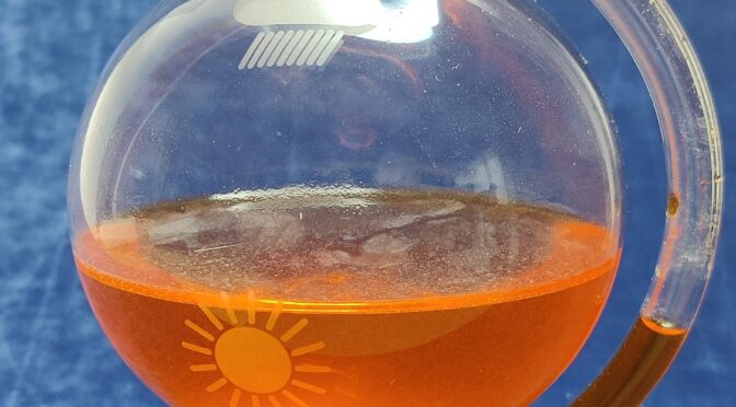
Again and again I look for simple, interesting things. This time I was fascinated by a measuring device or rather “display device”, whose operating principle is extremely simple and yet very effective. In addition, from my point of view, it is also an eye-catcher – it is the so-called Goethe Barometer. The best-known form is probably the bulbous glass hanging on the wall with a beak, similar to a watering can, in which the water level indicates the air pressure. I found a slightly differently constructed version of this glass on the net…

A little about the history of this structure:

To a gentleman named Evangelista Toricelli (1608-1647), an Italian physicist and mathematician, we owe the knowledge and proof that the air pressure is subject to fluctuations. He built the first barometer named after him in 1643. In 1644 he developed the mercury thermometer.

A small compensation area in the indicator tube protects against overflow

Der deutsche Dichter Johann Wolfgang Göthe, beschäftigte sich auch mit den Naturwissenschaften. Er machte selbst viele naturwissenschaftliche Experimente und entwickelte später ein einfaches, aber wirkungsvolles Barometer auf den Grundlagen des Toricelli.

Die Funktionsweise:

The barometer shows air changes quickly and precisely. When the air pressure rises, the water column in the indicator pipe falls and when the air pressure falls, it rises. This is made possible by the air trapped in the glass. The volume of the air always remains the same at a constant temperature. If the external air pressure rises or falls, the trapped air is compressed or expanded via the water column. Since the water cannot be compressed, it is the ideal medium to make the pressure differences visible. The height of the water column thus indicates the air pressure. If the air pressure is high in good weather, the external pressure is higher than the pressure of the trapped air and the water column decreases as the trapped air is compressed. At low air pressure, it can expand and the level of the water column increases.

the height of the water level in the pipe indicates the air pressure

This short time-lapse video shows the change in the water level when the air pressure changes:

Sony Video8 Walkman GV-8E

Loading

Sony GV-8E

Occasionally I browse flea market websites for vintage and retro devices from the 70s, 80s and 90s. If an absolute bargain is in sight, then I strike and sacrifice a few euros. This time I found a whole box of Sony portable media players. The whole thing just cost me the equivalent of a pack of Cafe. However, the state of the devices in terms of function is also unknown. A particularly beautiful piece (yes – that’s always in the eye of the beholder) from this box is the Videowalkman GV-8E from Sony. This is a portable, analog video player / recorder that has a VHF / UHF television tuner and an LCD monitor integrated in one device. While that may not be anything exciting today, the GV8E was a very nice and expensive piece of technology when it was launched in 1988. So the portable lands on my table and gets its 6V DC supply from the power supply. The disillusionment comes as quickly as the initial euphoria. The device shows no function despite the power supply being upright. It does not react to any key press, no LED lights up. (Somehow I was expecting this or something similar)

But the ambition is too great not to look inside the device and to look for the problem. I quickly started disassembling and roughly dividing the device into its components. The service documents can be found online, which are very helpful here.

GV8E in parts

After examining the block diagram of the entire system, the start of the troubleshooting was the DC / DC converter board. This board, covered by a shield plate, produces all the voltages required for the supply of the individual components from the 6V input voltage. A measurement on the test pins on the board showed that some voltages were missing. So there must be a problem here.

solder side of the DC/DC converter board
partside of the DC/DC converter boards

After removing the shield plate and inspecting the components, I noticed a defective 1.6A fuse (F103). This fuse protects the primary circuit of the switching converter. It can be seen from the plan that transistor Q114 was low-resistance and thus caused the fuse to trip.

extract from the circuit diagram of the DC / DC converter

The transistor is a 2SB1121 bipolar PNP transistor. Of course I didn’t have that in my collection. So thinned the component boxes for a suitable replacement …

replacement for the 2SB1121 is the PBSS5250Z

Then I found a PBSS5250Z, which has a slightly larger housing, but should do its job in the circuit.

defective Q114 desodered

Due to the larger design and the limited space available, I could only solder the replacement transistor upright.

Q114 renewed

Now a new fuse is still missing in the board. After installing and checking the other components in the affected circuits, the next function test was started. All boards electrically connected again and 6V connected to the battery terminals – and look – the Powersupply board starts up and the voltages are there. Now the GV8E can be switched on again with the power button, the LED also lights up and a quiet noise can be heard from the loudspeaker. However, none of the drive motors are running and the LCD monitor remains dark. The LED lights up briefly when the “Ejekt” button is pressed, but the motor responsible for ejecting the cassette compartment does not start. That means -> continue searching for errors. First of all I will take a look at the LCD monitor. It is quickly removed and dismantled. All the less pleasing is the condition of the board. Here the “decaying” electrolytic capacitors raged with their “body fluids”. (Of course this means the electrolytes)

Leaked electrolytic capacitors

The liquid electrolytes of the electrolytic capacitors have leaked over the years and have attacked the conductor tracks and also the solder joints. Sometimes it is so bad that small components, such as SMD transistors and resistors, fall off the board as soon as they are touched. At the latest now it is absolutely necessary to have the circuit diagram of the device at hand. Otherwise it will be difficult afterwards to correctly refill the missing parts. But first the old electrolytic capacitors had to be removed.

this is what the circuit board under the electrolytic capacitors looks like

With PCB cleaner I was able to remove the remains of the electrolytes and only then could I see the damage to the circuit board. Corroded areas had to be sanded with a glass brush and burned components had to be replaced. After cleaning again, the new capacitors (this time ceramic multilayer capacitors instead of the electrolytic capacitors) have found their place.

pcb with new parts

After this procedure the time had come. The next function test started. After reconnecting all plug connections and the power supply, there were further signs of life. The backlight (CCFL) started again and in the upper left corner it was “00:00” to see the flashing clock of the on-screen display … Unfortunately, that was all. The OSD display was very blurry and the rest of the picture was white. The brightness controls did not respond. So the board had to be examined “big”.

The board of the LCD monitor still had many broken conductor tracks, which had to be laboriously repaired with individual strands and enamelled copper wire. There were also some SMD components (resistors and transistors) so corroded at their connections that only an exchange helped. The result looks a bit wild, but another function test was finally positive.

fixed displayboard

After I reassembled the monitor, I went to the drive. Here, too, I first checked or renewed all SMD electrolytic capacitors, as ALL of them had really leaked out. Fortunately, the circuit boards here were not so severely etched and can be easily cleaned. Then the function test came. And unfortunately there were still problems here. There was no cassette ejection and no reaction from any of the drives. After studying the service manual and measuring many supply voltages, I was able to identify a processor as a source of errors. It is a SONY CXP80116.

Sony CXP80116

This chip controls all drives, leds, queries sensors, etc. It is also responsible for ejecting the cassette compartment. It controls a driver IC (bridge) via pins 20 and 21, which in turn supplies the charging motor. And exactly the two outputs remained at 0V. When the “Eject” button was pressed, only a few millivolts were measured instead of the 5V. So at first there was a suspicion that the driver IC has an error and is pulling down the outputs of the controller. So the outputs from the controller to the motor driver were separated and 5V directly connected to the motor driver input – and lo and behold, the loading motor was activated. So the problem is with the 80116. After some back and forth I was able to find one of these and exchanged it. Another test pleased me, because the cassette could be loaded again and the head drum started.

And the next problem already appeared. One of the two loading arms only drove half off and then got stuck. That means I also have to disassemble the mechanics of the drive. Said and done. Fortunately, it was only a small bolt that holds a drive lever. This had loosened and slipped out. So the problem was quickly resolved. Now I was finally able to do a function test again. And this time everything worked. The cassette was loaded, the head disk started, the tape was threaded and finally it could be played. After I had tested all functions, the GV-8E can be reassembled. Now he can go to the showcase as a “museum piece”;)


working again


Technical data of the GV-8E:

  • Video recording System: Rotierendes Zweikopf-Helical-Scan-FM System
  • Audio recording System: Rotierender Kopf, FM System
  • Videonorm: CCIR, PAL color
  • Kassettenformat: 8mm Videokassette
  • Bandgeschwindigkeit: SP: 2.0051 cm/s LP:1.0058cm/s
  • LCD Bildschirm: 6.2×4.6cm (3inch Diagonale)
  • Bildschirmtyp: TN LCD/TFT active Matrix mit 92.160 Bildpunkte
  • TV-Tuner: VHF Kanal 2-12, UHF Kanal 21-69
  • Anschlüsse: RF-Antenne, Video Input/ Output Chinch, Audio Input/Output Chinch (mono), Headphone 3.5mm Klinke
  • Energieversorgung 6V (Akku oder Netzadapter)
  • Leistungsaufnahme: 7.1W
  • Abmessungen: 129x67x213mm
  • Gewicht: 1.15kg ohne Akku
Typenschild des GV -8E


Cassette player/recorder SONY TC150B

Loading

Sony TC-150 cassette recorder

The Sony TC-150 is the newest, old member of the collection. Once again purchased as a defect device, this baby found a place in the workshop. After a quick inspection, it was immediately clear that the ravages of time were gnawing and, as is often the case, the drive belts became brittle or decomposed. Otherwise, the device is in perfect condition, hardly any scratches and damage to the case. The battery compartment was also clean. There are four belts of different lengths in the device.

belts to replace

Suitable replacement belts can be obtained, for example, from a large electronics store that is represented in Austria by six megastores. You will quickly find what you are looking for under the name “drive belt range” and “1.1mm edge length”. Replacing the straps is less quick. Here you should take at least half an hour and carefully take the drive apart.

The main circuit board must be removed in order to access the pulleys or to be able to unscrew them further. However, this is only possible if some lines are unsoldered. Only then you can fold up the board. Once that’s done, you can unscrew the retaining plates above the pulleys. They form the backing of the flywheels (capstan shaft). On this occasion, it is advisable to check the capstan shaft for dirt (due to belt wear) and damage, or it should be cleaned. The pressure roller must not be neglected either. In this model, both were in great condition. The pinch roller was neither glazed and brittle, nor contaminated with tape wear or shrinked. So I could put on the new straps. The main belt from the engine is put on with a rotation of 90 °. Here you should note the installation position of the old belt, if it still exists, or at least do a short test run after fitting the new belt.

If everything turns again (and especially in the right direction) then the assembly can be done. Solder the wires again, screw the circuit board and the repair is done. To have this man a test cassette, here are some parameters, such as tape speed or the tracking of the tape head, which are given and adjusted if necessary.

the TC150 after belt replacement
the VU-meter for recording level control to as battery meter


Technical data of the SONY TC-150:

Vendor:                                    Sony
Type:                                         TC-150 (Europa) bzw. BT-50 USA
year of production:           ca. 1977 – 1982 (according to various sources)
Modell kind:                          portable  Cassette Corder
Hauptprinzip:                      NF-Audio
                                                     Magnetbandaufzeichung/Wiedergabe
tape speed:      4.8cm/s
heads:                                      1 recording-/playback head
                                                     1 earase head (Permanentmagnet)
semiconductors:                8 tranistors, 5 diodes, 2IC´s, 1 FET
Power          :                           Outputpower: max 360mW
                                                     Powerconsumption : max 9W
Supplyvoltage:                   battery 4×1.5V AA, or accupack BP28
                                                     12V Caradapter bzw. 6V 4W wallplug
operationtime:                    2.5h at continous recording
Speaker:                                 dynamic 5cm Lautsprecher
Abmessungen:                    174 x 29.5 x 113 mm (BxHxT)
weight:                                    ca. 769g