When the brush stops turning – or: Repairing the Kärcher FC7

Loading

“Freshly mopped floors without having to vacuum beforehand: The FC 7 Cordless hard floor cleaner removes all types of dry and damp everyday dirt in one step.” (Original text kaercher.com)

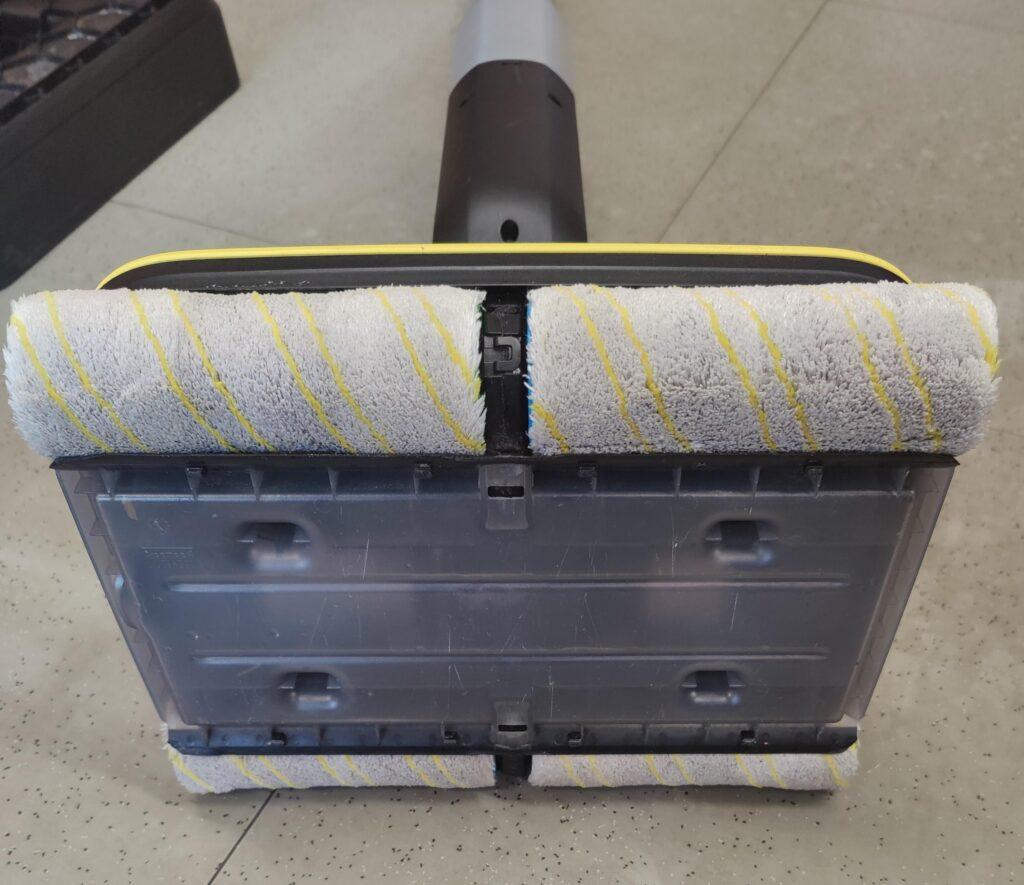
You get this product promise on the manufacturer’s website if you are interested in the FC7 electric hard floor cleaner. However, when this promise is no longer kept, I find out about the existence of these appliances. Because then I am asked to check why something is no longer working as it should. This is also the case here. The brushes (rollers – whatever these parts are called) no longer rotate, according to the problem description. Or to be more precise, they only turn sometimes when the bottom part of the moving handle is in a certain position. And since the handle (in which all the electronics such as batteries, BMS and operating elements are housed) can be moved within a wide range, it is reasonable to assume that there is a cable break or similar contact problem.

This is not exactly a complex problem, but perhaps one or the other is interested in how the problem can be solved with more or less effort.

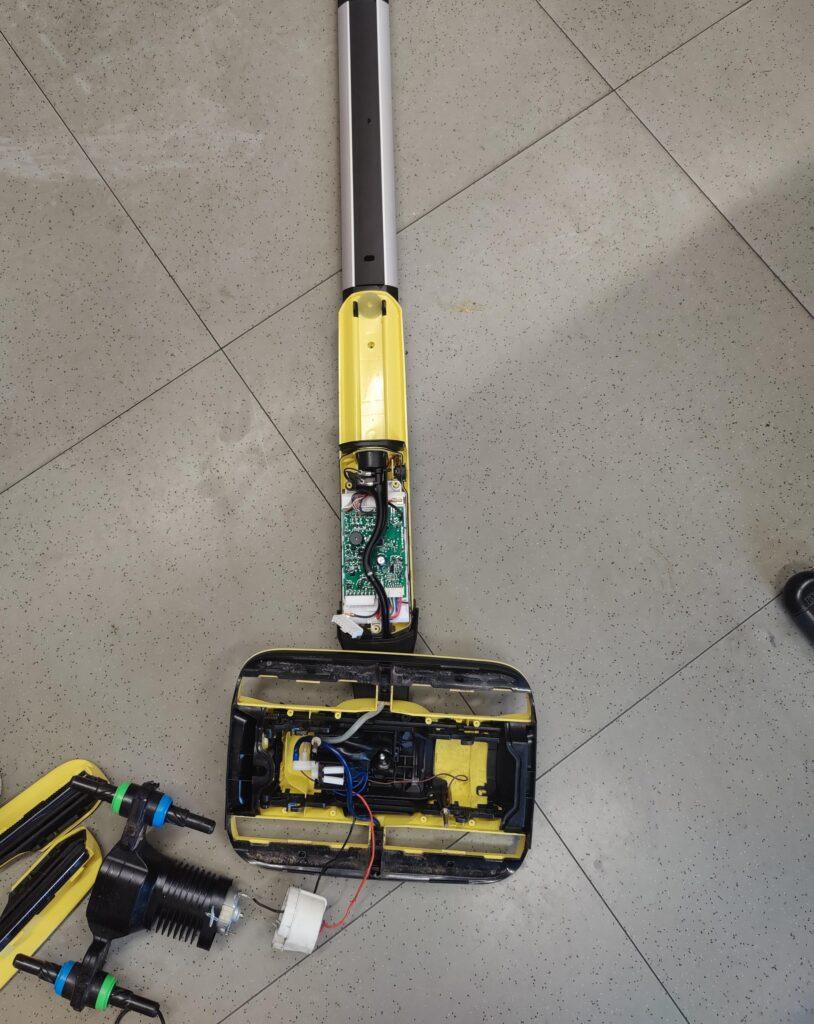
The first step is to remove the wastewater tank and the four cleaning rollers. The screws on the drive cover and battery cover can then be loosened and the covers removed.

Screws of the drive cover
Battery/electronics cover screws

Once the covers have been loosened, they can be removed. The circuit board with the BMS and the control electronics of the device can be seen under the battery cover. The 18650 Li-Ion cells are located underneath. The outlets to the bottom drive, to the control unit in the handle, etc. are plugged in.

Circuit board with BMS and control unit

The eight-pin plug at the bottom left of the picture must be disconnected. It connects the brush drive to the electronics. Six of the eight pins of the plug are occupied. One red and one black wire are used to supply the DC motor (yes, only a DC brush motor has been installed here and not a brushless one …) and two brown wires are laid to the pins that form the resistance sensor for the water level in the dirty water tank. Two blue wires control the solenoid valve of the water inlet.

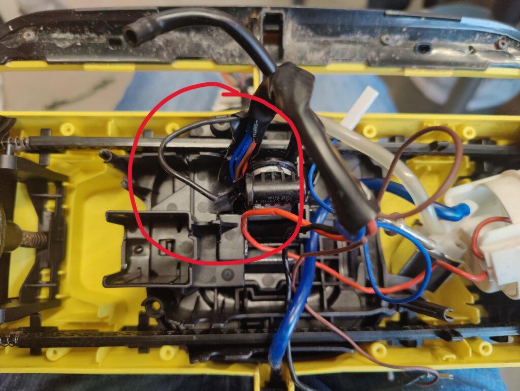
As the fault is in the motor drive (depending on the position of the handle, the motor may or may not turn), the fault may be in the cable connection from the circuit board to the motor. The fault was quickly discovered with the continuity test of the multimeter. The black cable to the motor was broken.

Broken cable (black wire to DC motor)

The breaking point is exactly in the area where the handle is movably attached to the floor unit. This is exactly where the wiring harness and the rubber hose for the water guide are inserted. Constantly moving the cable harness will inevitably damage and break the cables in the long term. Especially if the handle is used at very shallow angles, for example to clean the floor under boxes, chests of drawers, etc.

Wire soldered and insulated with heat-shrink tubing

I did the repair here by soldering the wire together and protecting it with heat-shrink tubing. I wrapped the damaged cable protection conduit with insulating tape. This should hold for some time. As the part will not last forever due to its design, the wiring harness should be completely replaced during the next repair. (as this is probably not available as a spare part, you will probably have to make one yourself – but then with more stable, highly flexible wires…)

The components could now be reassembled. Place the rollers in the green/blue colors on the drive hubs and screw everything back together.

Broken cable connections and torn toothed belts in the motor unit are obviously the most common faults with this appliance.

 

Geiger counter – kit from the Far East

Loading

II am always fascinated by the topic of radioactivity. More precisely, it is the measurement or detection of this ionizing radiation, which is produced by the decay and of atomic nuclei with the release of energy. A basic distinction is made between the energy (alpha and beta particles) emitted by the movement of the decaying particles (i.e. particle radiation) and the radiation energy that is transported as an electromagnetic wave (gamma radiation and also X-rays). These types of radiation have different energy densities and ranges. Depending on the type, they are more or less easy to shield. Alpha radiation is particle radiation that is strongly slowed down by matter (air, water) and no longer penetrates a sheet of paper. However, these particles give off the energy over their very short distance. This is particularly dangerous if these particles are inhaled or radiate on the upper layers of the skin. Gamma radiation in turn penetrates matter very easily like a radio wave and can be shielded most effectively with lead. It goes without saying that this type of radiation is anything but harmless.

You cannot see, smell, taste or otherwise perceive this radiation directly, but the danger is still there. With relatively simple techniques, however, these decay processes can be made visible or audible and counted.

This has been done for a long time with a so-called counter tube or, thanks to modern technology, with semiconductors. A P-N junction is operated in reverse direction and the very small reverse current is measured with the exclusion of light (i.e. darkened). If high-energy radiation hits this P-N transition, the current flow is increased for a short time and can be detected.

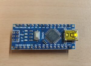
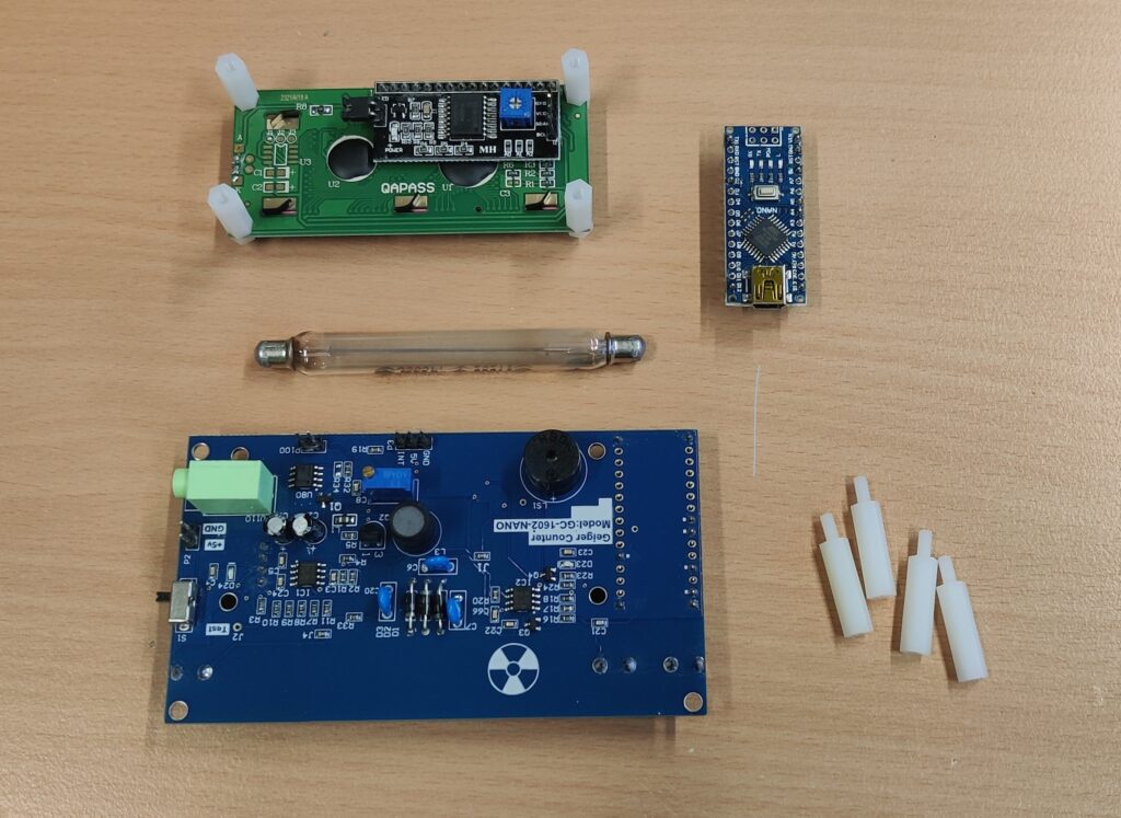
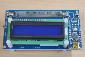
Whenever the opportunity arises to get a detector very cheaply, I of course take it. So this time too. I had to look at a simple kit based on detection using a counter tube. The kit comes from the Far East and consists of a base board, an attached Arduino Nano and an LC display that is also attached.

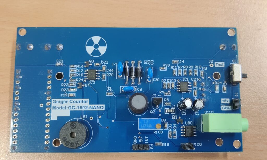
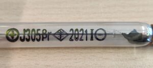
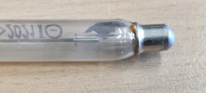
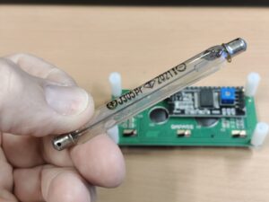
All components required for detection are on the mainboard. This includes, among other things, the generation of high voltage for the counter tube, which is implemented using a simple boost converter circuit driven by a 555. To attach the counter tube to the mainboard, the designer of this board chose simple glass tube fuse holders. They don’t fit exactly, but they can be stretched so that they hold the counter tube firmly in place. Incidentally, the counter tube is a J305. It is approx. 90mm long and has a diameter of almost one centimeter.

The counter tube works with an anode voltage of 350V to 480V. Below I have listed the specifications from the data sheet:

  • Anode voltage: 350 v bis 480 V
  • Type: J305 Geiger-counter tube
  • Cathode material: tin oxide
  • Wall density: 50 ± 10 cg/cm²
  • Operating temperature range: -40 °C bis 50 °C
  • Diameter: 10 mm (±0,5 mm)
  • Length: 90 mm (±2 mm)
  • Self-background radiation: 0,2 pulses/s
  • Sensivity to γ-radiation: 0,1 MeV
  • Current consumption: 0,015 mA bis 0,02 mA
  • Working voltage: 380 V bis 450 V
  • γ-radiation: 20mR/h ~ 120mR/h
  • β-radiation: 100 ~ 1800 Pulse/min.
  •  100 ~ 1800 pulses/min.

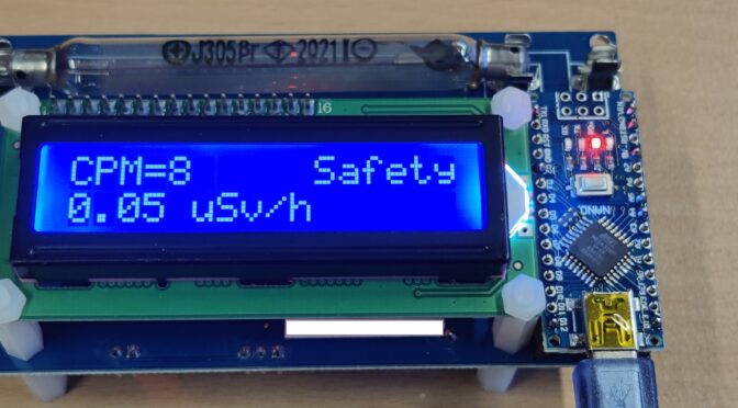
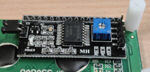
The signal detection and processing of the signal also takes place on the mainboard. The recognized impulses are reproduced via a small piezo loudspeaker. In order to be able to count them, you don’t have to sit in front of the loudspeaker with a stopwatch and count the beeps every minute – no – that is done by a microcontroller, which, as is common today, consists of a finished board. Here the designer has chosen an Arduino Nano (or nano replica). In turn, a program runs on it that counts the impulses and also shows them nicely on a two-line LC display and ideally also converts them into µSievert / h. To transfer the pulses to the Arduino, the level of the signal is brought to TTL level and switched to the interrupt input of the Arduino. The LC display uses the I2C output of the Arduino. The lines for this are only led from the socket strip into which the Arduino is plugged via the mainboard to the socket strip for the display. To supply the whole system with voltage, the 5V from the USB port of the Arduino are used directly. Optionally, the 5V can also be connected to the mainboard via a connector strip.

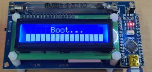
Once everything has been assembled and the USB supply is connected, there is first of all a short waiting time during which the high voltage is built up. Here the programmer has come up with an animation that shows “Boot …” on the display.

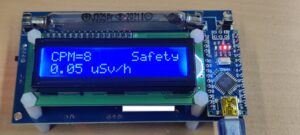
And then it starts. The Geiger counter is ready for use and begins to count. As a test I only have an old clock with hands painted with radium paint. There is at least a clear change in the number of detected counting pulses when the watch is brought near the counter tube.