
Geiger counter – kit from the Far East
![]()
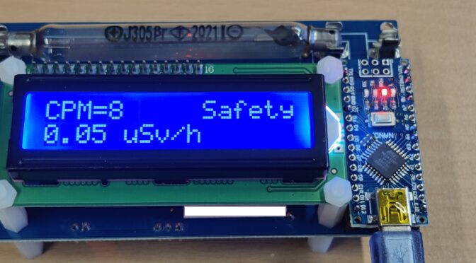
II am always fascinated by the topic of radioactivity. More precisely, it is the measurement or detection of this ionizing radiation, which is produced by the decay and of atomic nuclei with the release of energy. A basic distinction is made between the energy (alpha and beta particles) emitted by the movement of the decaying…
Read more


Recent Comments