Tag Archives: RetroComputer

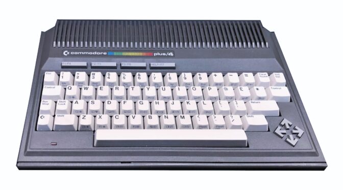
I’m looking for ONE button from the Commodore Plus4

Loading

The title says it all. I am looking for the RUN/STOP button for a Commodore Plus 4 computer. The model that I prepare is already finished except for this missing button. I’ve looked on the bay and at flea markets, but nobody can help me there, or you can get whole keyboards, but unfortunately at an unfair price. So if someone has a Plus4 standing around to slaughter and can help me with the key at a fair price – I would be very happy.

8-Bit Generation: The Sinclair ZX-Spectrum

Loading


The ZX-Spectrum from SInclair

On April 23, 1982, the Sinclair ZX Spectrum has been marketed by Sinclair Research. [Source: Wikipedia] He was then sold at a price of 140 euros or 194 euros. The two prices refer to the 16kByte version or the 48kByte version. 16kByte and 48kByte are the sizes of the RAM memory with which the computers were equipped. The ZX-Spectrum is the successor to the Sinclair ZX81 and the predecessor of the ZX-Spectrum Plus and Sinclair QL.

The small computer (the dimensions are just 23.5cm * 14.5cm * 3cm) is powered by a Z80A CPU running at 3.5MHz clock speed. The ULA (Uncommitted Logic Array) is the largest chip on the ZX motherboard. She is responsible for the graphics, the audio IOs (for loading and saving programs on tape) and keyboard input. Then there are, depending on the version, the DRAM chips (upper and lower RAM) on the board and another ROM IC, which houses the BASIC interpreter. The small calculator can draw colorful graphics on the screen with a resolution of 256 x 192 pixels and 15 colors. The image output is sent to the antenna input of a TV via a built-in RF modulator. With picture output but I really only the “picture”, because for the sound is not the audio channel of the TV set used. But there is a small speaker on the motherboard, which outputs the sounds of the computer. Which in turn are not generated like in the C64 in a separate chip (SID chip) and that in several voices – no, the MIC / TAPE pin of the ULA is used, which simply switches the speaker via a transistor to 5V. This can then be used to generate simple “beep noises”. Of course, from a current point of view, that’s nothing special at all, but for those who were confronted with it in their childhood, there are certainly some memories associated with it. So also for me. At least then I had the opportunity, with my brother to borrow such a device from a friend. Then of course it was – how can it be otherwise – played. Titles such as “Manic-Miner”, “Ant-Attack” or Flight Simulator were among the most frequently loaded cartridges. Yes – cassettes. At the time it was common to buy the programs on an audio cassette. A simple tape recorder was connected to the ZX-Spectrum via the headphone jack and the LOAD “” keys were entered via the rubber keys on the ZX. Then you had to press on the tape recorder only more play and it could start. The prerequisite was, of course, that the tape speed and the adjusted volume level fit. Only then was the loading of the program successful and the game started. The loading times were from two to often more than ten minutes depending on the program.

datarecorder for loading and saving from programmcode

In my 8Bit – Retrorechner collection was missing until now the complete series of Sinclair calculator, but finally I could make a bargain and buy a whole set with ZX-Spectrum, joystick module, a data recorder and many original game cassettes. I would like to briefly describe the preparation and restoration of the ZX here. If you get your hands on a computer with an unknown background, which has been lying around in a cellar for the last 30 years, you should not try to put it into operation. If he is not already, that could be his death. Because, as always, there are some parts that can age and change their parameters. Someone could have tinkered with it before to repair or retool something. In this case, the case was dusty and dirty, but there were no missing screws, dents or externally apparent retrofits, such as buttons or plugs. So I could solve the case screws.

The keyboard foil was quickly pulled out of the clamping bushes and the lid with the rubber keys removed. Now the inner life of the Spectrum revealed itself – and what can I say – 1A. Everything in original condition. No repairs or tinkering have been done on the device yet. So I first started cleaning the body parts. The keyboard is easy to disassemble. In this revision of the spectrum (ISSUE 4A), the metal sheet that holds the rubber mat in the housing is fixed with four “brass bending tabs”. These can be easily bent back and remove the sheet.

Frontblech und Gummitastenmatte enfernt
freigelegte Tastaturfolie

The housing parts were now very easy to clean. I rinsed it with soap under lukewarm water. Also, the residue between the rubber mat buttons could be easily removed. While the parts were now set aside to dry, I dedicated myself to the motherboard.

Mainboard des ZX-Spectrum 48K Issue 4A

Here all solder joints were clean, no traces of foreign intervention and all parts still in original condition. So I could start directly with the first exams. An ohmmeter was used to test for short circuits in the power supply area. If you look at the circuit diagrams of the spectrum, you can quickly see that the computer is supplied with an input voltage of DC9V. Here the assignment of the power supply socket is to be considered. Here, the plus pole is not the inner pin but the outer ring of the connector. This is especially important if the original power supply is no longer available and you take a replacement. The further structure of the supply concept is as follows: From the 9VDC the + 5V supply is made via a linear regulator 7805. Using a DC / DC converter circuit consisting essentially of the components TR4 and TR5 and a small transformer (cylindrical coil with two windings), a 12VDC and further a -5VDC power supply are generated. Special attention should be paid to this area, as a wrong or missing power supply can damage other components (especially the DRAM ICs). To do this, use a diode tester to test the transistors for their conduction and blocking behavior of the PN junctions. The easiest way to test the small transformer is to use the ohmmeter for low-resistance behavior of the respective winding and high-resistance behavior between the primary and secondary windings. If everything is alright here, one tests the output of each of the three voltage sources with respect to the ground 0V potential. Here are the following guidelines to measure:

  • Eingang des Linearreglers (9V) gegen GND -> ca. 100k-150k
  • Ausgang des Linearregler (+5V) gegen GND oder an Pin9 des RAM ICs -> ca. 300 – 500 Ohm
  • Pin1 des RAM ICs (-5V) gegen GND -> ca. 300 Ohm (im 400Ohm Messbereich)
  • Pin8 des RAM ICs (12V) gegen GND -> ca. 2.6k bis 2.8kOhm
Elektrolytkondensatoren erneuern

In the next step, the over 30 years old axial electrolytic capacitors are exchanged. This is a pure precaution, because as everyone knows, these parts like to change their values ​​with increasing aging or run out. And what leaked electrolytes can do so everything, I have already shown in older posts. In order to allow the ZX a longer life again, all Elkos are exchanged.

die alten Elkos
Mainboard mit neuen radialen Elkos

Once this work is done, then the exciting part begins. The power supply is switched on. It is best to supply the ZX with a laboratory power supply with adjustable current limit. He may take after switching on not more than 750mA at 9VDC. If that also fits, the voltages can be measured (best on one of the lower RAM ICs). It should be measured at PIN1 -5V, at PIN9 + 5V and at PIN8 12V.

Conversion of the RF modulator to video output

In order to be able to connect the ZX-Spectrum to a display unit, there is the RF modulator, which modulates the internally generated composite video signal onto a UHF channel carrier in order to operate a classic analogue TV. Since television receivers with analogue tuner are now hardly available anymore, but many TV have at least a SCART or video input, the RF modulator of the ZX-deactivated. The former antenna socket is converted into a video output. First, the two wires coming out of the modulator are unsoldered from the motherboard. (These are + 5V and CVBS). Then inside the modulator, the pin of the resistor is unsoldered from the inner conductor of the antenna socket and bent away. Thus, the modulator is completely disconnected from the circuit. Now only the CVBS output from the motherboard needs to be soldered via a capacitor to the inner pin of the socket. The capacitor should be around 100uF. It serves as DC decoupling of the signal.

When all this is done, you can now connect and power up. In my case, it was a complete success. The Sinclair reported immediately with its gray-screened startup screen “(c) 1982 Sinclair Research Ltd” Next, I tried an old original game (backgammon) on the tape recorder (data recorder) to load into the ZX. That did not work for the time being. Sometimes a part was loaded, then again not and it came to “Tape Error” messages. So the tape recorder was also quickly overtaken. A new belt made for a better synchronization of the band and a head cleaning for nicer levels of the output signal. But even now the shop did not work. (this reminded me strongly of the time, where often a long time was trying to load a game) So I saw with the Oszi the output signal and especially the period of the initial signal (the first whistle on the band :))


Einstellung der Bandgeschwindigkeit

Here it was, the problem. The frequency of the initial signal was about 890-910Hz. That means the tape runs way too fast. The problem is resolved quickly. Almost every cartridge drive has a small potentiometer to adjust the tape speed of the servo drive. Even so in this case. The frequency should be around 800Hz. The result was then:


Here is the program from mp3 file: backgammon


YouTube, and interesting technology favorites

Loading

This time, I’m not going to talk about a project or an “old equipment concept”, but would like to introduce some interesting users or their contributions from the YouTube portal. These are contributions from the field of computer, technology and science, which I personally like to look at.

First and foremost, I would like to mention the legend of modern computer history, which has fascinated me since my youth. The ComputerClub from WDR times with Wolfgang Rudolph and Wolfgang Back. The two moderators moderated the program Computerclub from the beginning of the 80’s to 2003 at Westdeutscher Rundfunk. In the topics, the two men are generally concerned with computers and peripherals, new developments in the field of electronics and present all sorts of things here. Many broadcast recordings are archived on YouTube, including by user janbras.

On 22 February 2003, the last broadcast was broadcast on WDR.

But the two protagonists have not given up the computer club and let him resurrect on July 24, 2007 on a German private broadcaster (NRW-TV).

However, the private broadcaster NRW-TV had to cease its operation in 2016 and so the program was Nr.186 recorded as the last in the studios of NRW.

But Wolfgang Rudolph has managed by fundraising to set up his own studio and now produces the CC2 from his private studio on his own.

In the background, a lot has changed, which confused the viewers and freaks a bit. Parallel to the broadcasts existed the page cczwei.de which was filled by both gentlemen. After 13.12.2016 suddenly a new page appeared. The new domain cc2.tv has been created. The now operates Rudolph alone. The domain cczwei.de continues to be operated by Mr. Back. He is assisted by Heinz Schmitz, who is now producing YouTube broadcasts with Mr. Back. Apparently, there were sufficient reasons for the gentlemen to part with years of community work. There never was an official explanation.


From the computer area, the guys from VirtualDimension report. They call their channel VD Hurrican and produce the formats: Virtual Worlds, Back in Time, Retroplay and On Site. The contributions are absolutely professional and mainly deal with home computers. With a lot of background information the old 8 and 16 Bit’er are presented here. Gameplay as well as fair reports and contributions from community events are also part of their repertoire. As an example here a link to the unboxing of an Amiga500 and its history. On the occasion of their 1000th subscriber on YouTube, they have published a 1000-subscriber special with a studio tour.

From the Australian continent, Dave Jones, also an inveterate technician, blogs. On his YouTube channel EEVblog, He also introduces electronic devices, explains their structure and operation. A special category in his channel are the so-called Mailbags. Here, Dave receives packages from people in the community who he opens in front of the camera and presents their content. This can be old computers and boards, or even new developments and prototypes of startups that are presented here.


A slightly different channel is that of an Englishman. He calls himself Photonicinduction and shows experiments with high performances. All sorts of appliances, such as vacuum cleaners, heating lamps, washing machines, loudspeakers, etc. are operated to the limit of their maximum performance data – and far beyond. The end of the device through destruction is the goal here.


Amiga – Genlock cable

Loading

Some time ago I wrote a post about the Amiga Genlock “VESONE”. It can be found under the title “Amiga and Genlock”.(link)

Apparently there are still some people who own such a device and want to use it again. But since, as with me, the necessary cables, software etc. are not necessarily stored where the device is, it can be difficult. I thought to myself that it doesn’t matter, because what is the Internet for – but far from it. You won’t find anything. I noticed that now when a blog visitor asked me about the pinout of the RGB to genlock cable. I didn’t find anything on the net. But deep in the boxes in the cellar in various cable boxes, I was lucky. The cable appeared. In order to share the pin assignment with other retro fans, I have drawn out the pin assignment and put it online here.

So here are the pictures and the pinout (Amiga_VESGenlock_Cable)