
Radioreceiver in a retro look – Update: The case
![]()
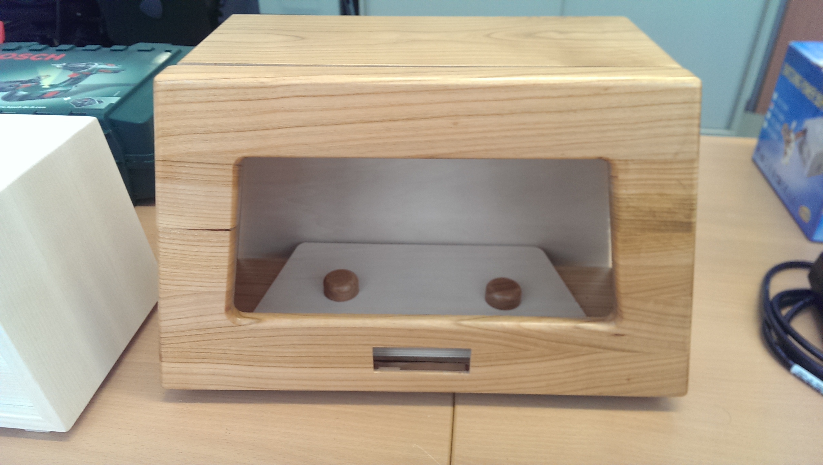
It’s time! The first picture of the absolutely real wooden housing for radio electronics is here. A beautifully crafted housing made of glued elements. This work comes from Gebhard’s hands, a master carpenter from the Upper Carinthian region;) Jetzt kann das Nostalgie-Radioprojekt wieder einen Riesenschritt nach vorne machen. The case is on our table. First,…
Read more


Recent Comments