![]()
 One project that had long been of interest to me was the detection of radioactive radiation. After the horrible powerplant accidents in Japan, this idea was recalled. I could still vaguely remember owning an unused counter tube somewhere in my old workshop cellar. – After some search it turned up :). Thanks to the Internet and the search engines, a data sheet was also found quickly. The counter tube is a ZP1400. A self-extinguishing Geiger-Müller counter tube with mica window. The tube is according to data sheet with neon and argon filled as quenching gas. The operating voltage is 400 to 600V. The capacity between anode and cathode is about 2pF. With these and other information from the data sheet i now can tinker a circuit to take the tube in operation. I have used this small project to introduce our apprentice to the board layout at the same time and to get acquainted with the creation of small programs on the Arduino Uno microcontroller board. In this post I introduce only the “old-fashioned” circuit, where only the impact of ionizing radiation is made audible to the count wire. (the typical crackling). This circuit then provided the basis for the apprentice to realize the count of the pulses with the microcontroller and to visualize it on a two-line LCD.
 |
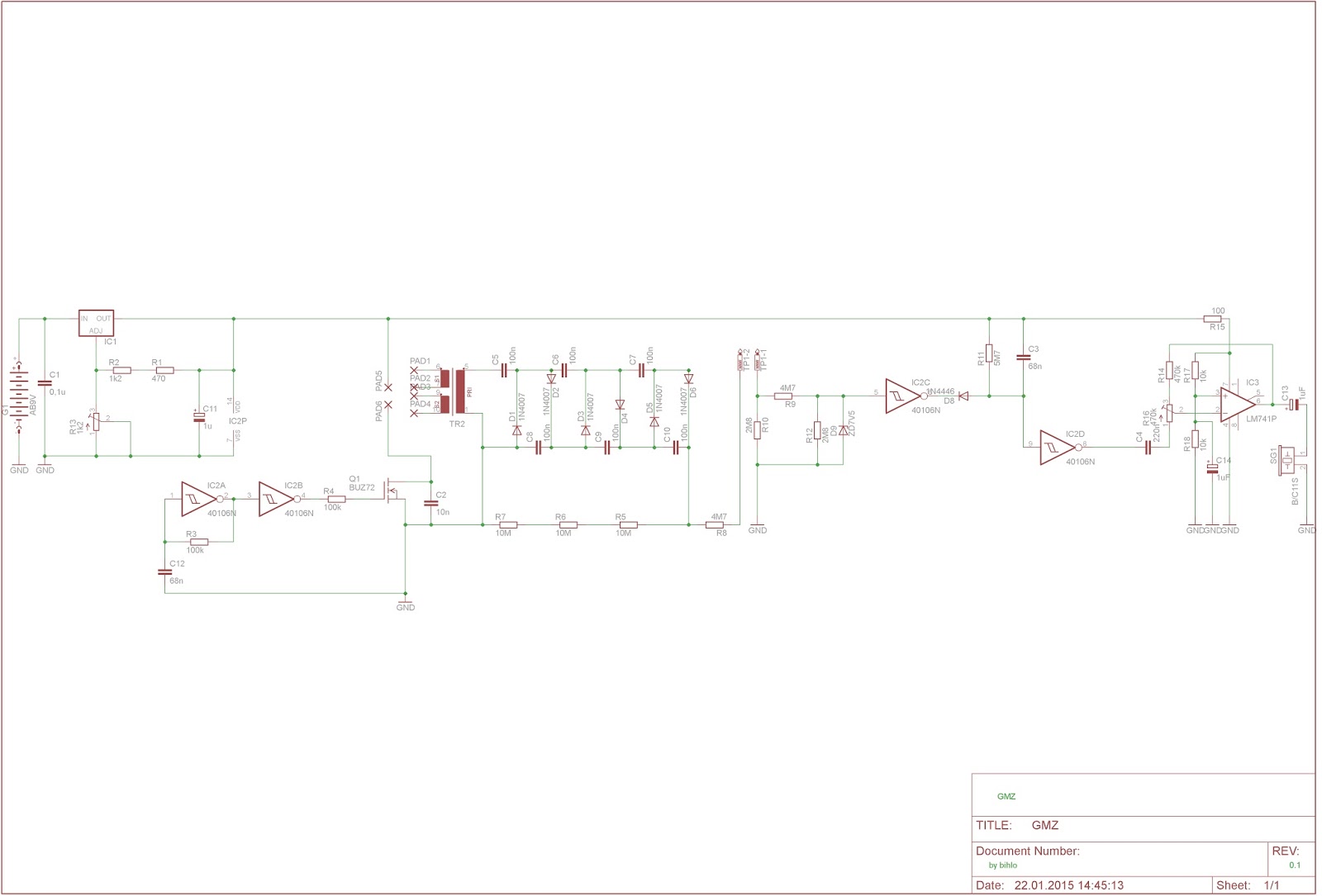
| Wiring diagram with high voltage supply and pulse amplifier |
Using the well-known layout software Eagle, I have drawn a circuit in which the high voltage is again generated by a switched transformer and subsequent Greinacher cascade. The control takes over this time no 555er, but simply a feedback Schmitt trigger. The time base is set via the coupling resistor and the capacitor. Thus, the high voltage is available for the counter tube. In order to be able to count the impulses, two factors are ensured. The impulse must not exceed a certain height. (Otherwise the following electronics may die) and the pulses should be audible (boosted). So the peaks are limited with a zener diode circuit and put into a “nice” shape with Schmitt triggers and then led to an op amp. At the output of the op-amp then hangs first a small speaker …
 |
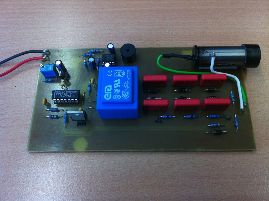
| Arrangement of components on the PCB |
After the circuit board was etched and assembled, it was time to test. But with what? I needed some weak source. I held all sorts of items in front of the counter, but it did not change much. There was a cracking sound from the speaker four to eight times a minute. So I started researching the net again. And came across the term “radium color”. This is the self-luminous color with which the dials of old watches were painted, in order to be able to read the time even in the dark. This information gave me an idea. From my grandfather i inherited once an altimeter of a WW1 aircraft (manufacturer LUFFT) whose dial might have been painted with that kind of color. So get out of the showcase and held in front of the counter tube … The result can be seen in the video.