
Radio in retro-look – KnowHow for the apprentice – Part 1
![]()
THE IDEA FOR THE PROJECT
A project idea that came to my mind as an ideal apprentice project is to plan and build a radio receiver. With this project, our apprentice should apply the acquired skills in a practical way and set up an FM radio receiver according to the components to be used.
This was done gradually. I came up with the concept in the following parts:
THE AMPLIFIER
First, a simple class A audio amplifier should be built. The apprentice should build the amplifier according to the circuit on the breadboard, metrologically examine and understand above all. In the next step, the Class A amplifier became a Class-AB amplifier. Again, the task of the apprentice was to understand the operation and optimize the breadboard function pattern so that a (not metrologically) at least reasonably “good” acoustic result was achieved.
 |
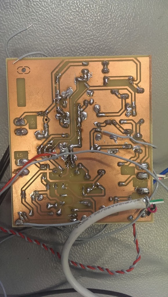
| First functional pattern of the “power output stage” |
When this succeeded after some time, he got the task to transfer the determined circuit into a layout tool and expand it to a second channel, while also creating a power supply concept. The power supply should not only supply the amplifier output stage, but also for other components (such as microcontrollers, USB interfaces and what ever came to mind) a + 5V and + 3.3V DC supply available.
After many layout designs, he then presented me with a layout in which the components were symmetrical and technically reasonable (Trimmpotis should be accessible …) were arranged. So he was allowed to make the layout as a functional sample. (etch the board, populate it and try to get it all working).
The learning effect was gigantic: D, because in the implementation of theoretical circuits to a simple breadboard construction and then to the “printed” circuit on the print, there is a lot of sources of error. And they also want to be found and corrected. Our trainee was able to practice patience and precise work.
But in the end, the 440Hz sinewave of the frequency synthesizer sounded from both connected speakers …
Now it was time to think about the signal source, the actual receiver.
THE FM RECEIVER
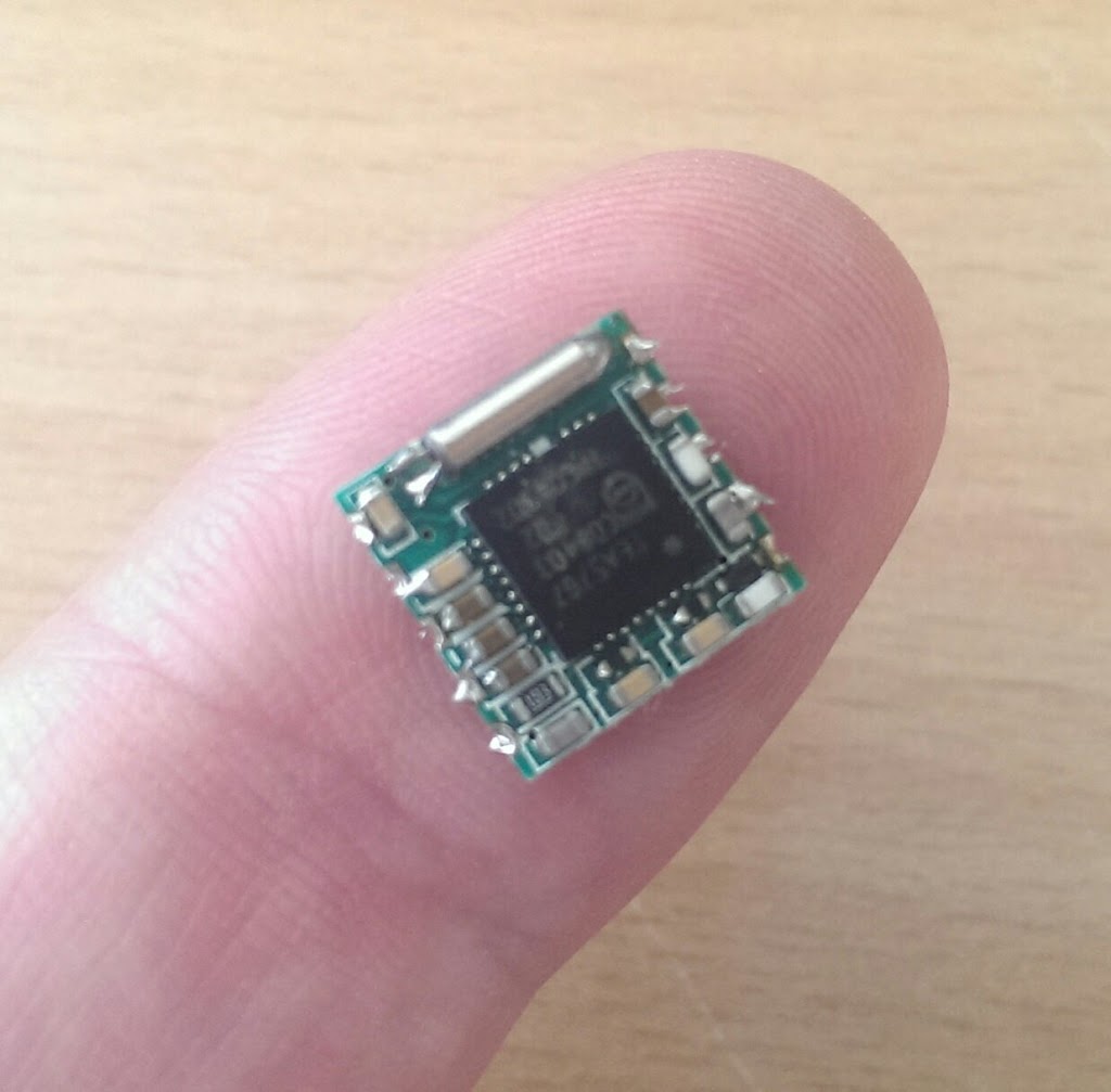 |
| FM-Receivermodul |
In a Chinese online shipping I discovered an FM receiver module with a very compact design (a print with about 12x12mm) on which a complete receiver is integrated. The module is called TEA5767 and uses the eponymous Philips FM receiver chip.
The connections to the module consist of power supply, audio L and R outputs, as well as an I²C bus to control or set the reception frequencies and an antenna and Muteeingang. So ideal to realize a signal source for our amplifier. But that raised further questions.
How should one generate the control signals for the I²C bus, how should the tuning of the transmitters be done, how should the device be operated by the user at all? For all these questions, there is a simple answer: Take a microcontroller. And as the apprentice likes experimenting with the Arduino UNO board, I decided to use an Atmega328, the Arduino UNO controller.
THE HEART OF THE RADIO – THE CONTROLLER
The microcontroller should therefore take over the complete management of the radio, thus fulfilling the following functions:
- set the stations (generate I²C commands and send them to the radio module)
- save the tuned stations (in the internal EEPROM of the controller)
- show all information on a LC display
take over the volume control - generate operation by means of a push / turn wheel (incremental encoder with touch function should take over the entire operation of the radio)
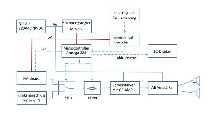 |
| blockschematic |
So we had to extend the circuit by a few components. The audio output of the FM module had to be pre-amplified. This was done by a small AudioOPAmp. To realize the volume control via the microcontroller, simply a “digital potentiometer” X9C102 was used. It is controlled directly by the controller with a “direction input Up / Down” and a “count input”. Internally, this IC consists of 100 resistors connected in series, whose “tap” is determined by counting input. So a simple matter to control the signal level of the preamplifier in 100 steps.

