![]()
At the beginning of my blog, I talked about a small project with an oscilloscope tube. Since there are still pictures in the archive, I do not want to withhold it from the blog here:
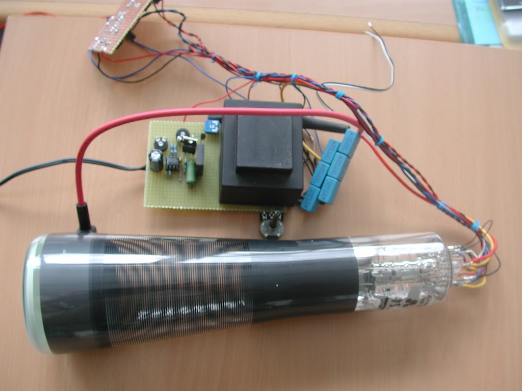 |
| Cathode ray tube with high voltage generation |
The Braun tube – as it is e.g. is present in a cathode ray oscilloscope – has two capacitor plates each to deflect the electron beam. (X and Y baffles). The tube is a Philips B7S 401 oscilloscope tube. For the sake of completeness, I list some technical data here:
- Indirectly heated cathode, heating voltage Uf = 6,3V
- Heating current If = 90mA
- time for heating kathode tK =1min
- total accelerationvoltage Ua= 1,2kV
- Base point tension of the post-acceleration resistance Ug5 = 300V
- acceleration voltage Ug4 = 300
- focusing deltaUg3 = 20V … 50V
- pre acceleration volatage Ug2 = 1,2kV
- reverse voltage Ug1 = -30V … -80V
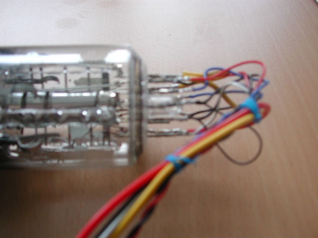 |
| Connections on the tube socket |
The aim of the project was therefore to put the small tube back into operation and to lure her a few pictures. So a drive had to be built. Since the supply voltages are quite varied (6.3V to 1200V), this problem had to be solved first. With a NE555, a few components and an old transformer (240 / 12V) a high-voltage power supply was tinkered.
The principle is simple: A DC voltage is switched on and off very quickly with a small circuit. This switched DC voltage in turn connects with a power transistor, the output side of the transformer. (ie where normally the 12V are applied now fed) The ratio of the transformer works in the other direction :). So arise at the exit ever a few hundred volts. (depending on the switching frequency). In order to produce over 1200V, I have connected a cascade (capacitors and diodes). (Functionality)
So now all voltages necessary for the operation of the tube are available to produce an electron beam. With the aid of adjustable voltage dividers, the beam current and the grids for brightness and image focus can be set.
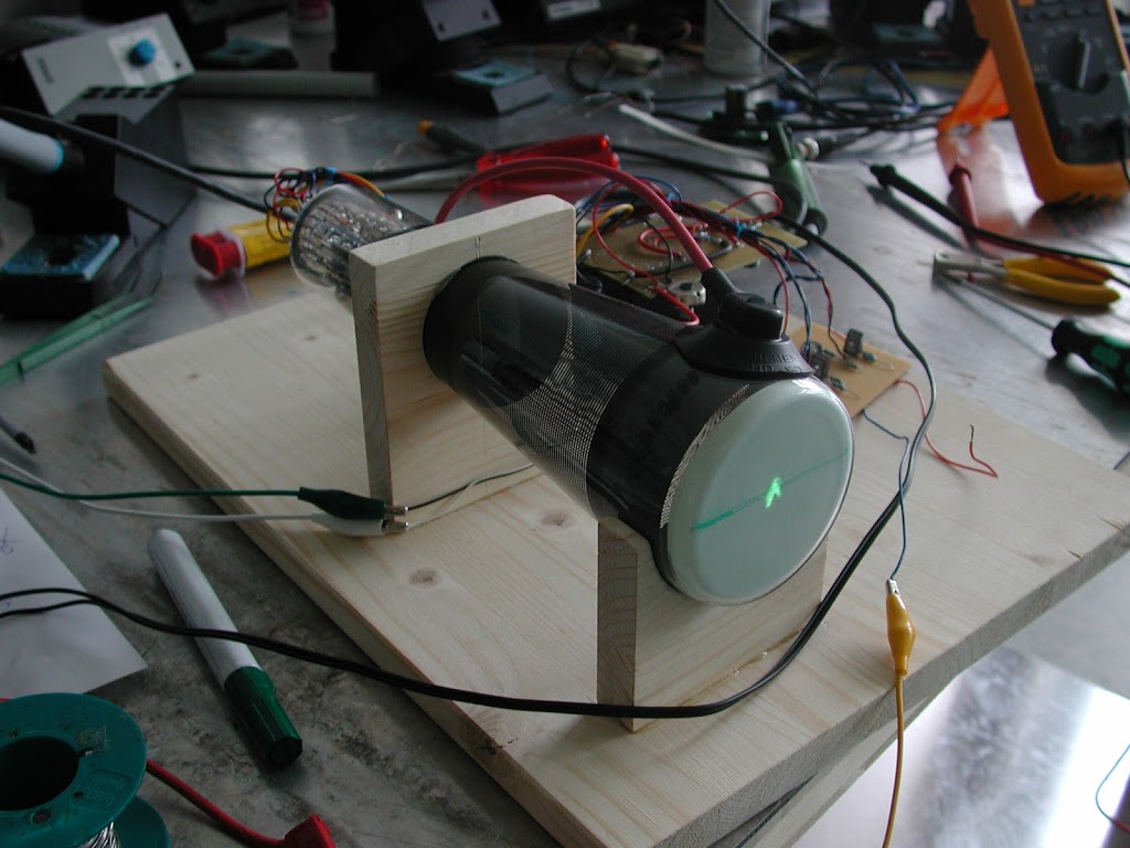 |
| the fist illuminated spot |
The voltages for the baffles are also taken from the high voltage supply and controlled by transistors. Thus, a deflection of the electron beam in both axes is possible.
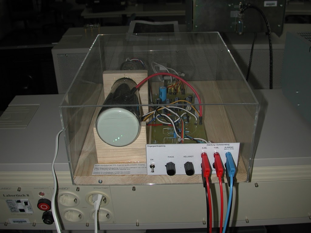 |
| Plexiglas housing |
The transistors in turn are controlled by a small pre-stage, which is fed externally with a voltage of -5V to + 5V – the control voltage for the deflection of the light spot. This control voltage input exists for both axes. I added another input to switch the electron beam to “bare”, ie dark. For this purpose, a corresponding voltage is applied to the corresponding grid, which previously block the electron current to the anode.
 |
| connections |
Thus, the tube can now be controlled directly from the outside, for example, by means of analog outputs of microcontrollers (Arduino, PIC, etc.) or NI DAQ cards with the extra-low voltages available there. After the first positive test runs with the breadboard electronics I then constructed a clean board and mounted the whole construction on a wooden board and covered with a transparent Plexiglas housing.
All connections are routed via banana sockets to the outside. For example, you can easily draw Lissajous figures on the screen …
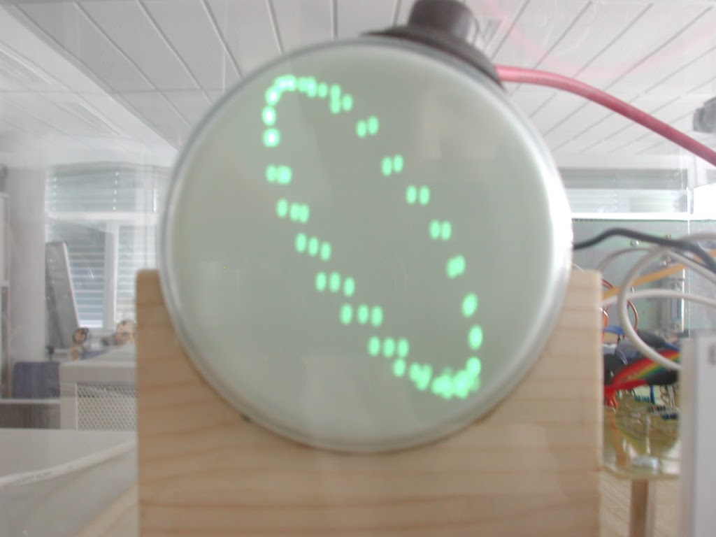 |
| Lissajous-figure done withe NI-DAQ |