
Radio in retro-look – KnowHow for the apprentice – Part 2
![]()
… to realize the volume control via the microcontroller, a “digital potentiometer” X9C102 was simply used. It is controlled directly by the controller with a “direction input Up / Down” and a “count input”. Internally, this IC consists of 100 resistors connected in series whose “tap” is determined by counting input. So a simple matter to control the signal level of the preamplifier in 100 steps ….
Continued from Radio Part 1
The controller should now be operated via a push / turn wheel (rotary encoder with push button). In order to be able to evaluate the direction of rotation of rotary encoders, a second pulse output is required. The two pulse outputs must be shifted in their sequence depending on the direction of rotation (phase shift). In order to convert the pulse sequence into a direction signal and a clock signal, we have set up a small decoder logic using a JK flip-flop and a Schmitt trigger / inverter …
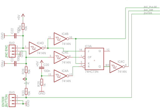 |
| Turnwheeldecoder |
The outputs of the decoder logic are now passed directly to three microcontroller inputs. Thus, now a suitable program can be created, which provides a simple menu-driven user interface. The parameters are displayed on a two-line LC display. The outputs of the controller, in turn, control the “digital potentiometers” for the volume setting and, of course, the I²C bus, which sends the commands to the FM module. An additional output allows the switching of a relay, with which, for example, the audio input from the amplifier can be switched between the FM module and an external signal source. The LC display is connected to the controller in 4-bit mode and the backlight of the display is also switched by the controller.
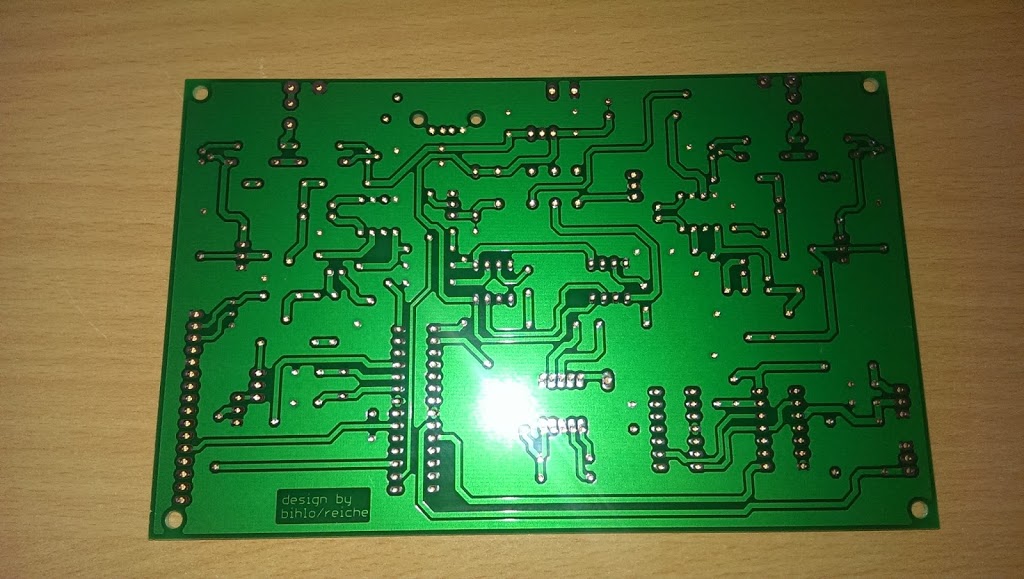 |
| PCB fresh from production |
After all these functionalities had been defined, we were going to transfer this information to the Layout Tool or the schematic.
Finally, a layout was drawn and made. Subsequently, we could start with the assembly of the board and then carry out the first commissioning. After the adjustment of the amplifier quiescent currents, the development of the Arduino code began. Here, the work is extremely facilitated, since there are many finished libraries here, which can be used directly for its purposes. For example, the only challenge with getting an LC display up and running is to connect the few wires to the uC (microcontroller) and pinpoint the pins in the code. Everything else is done by the library. With this simplification, the functions are then implemented quickly and the first test run can begin.
 |
| ready assembled PCB |
As a result, the software will be even better – perhaps saving multiple stations, and so on. But the next step will be to build the board into an enclosure modeled on the old radio tube radio receivers. It should be made of solid wood. The operating and display elements are to be installed in an aluminum plate placed on the front of the housing … (Another post on this blog will follow.)
The first functional test can be seen in the video below …

