
DAT-Walkman Sony TCD-D3
![]()
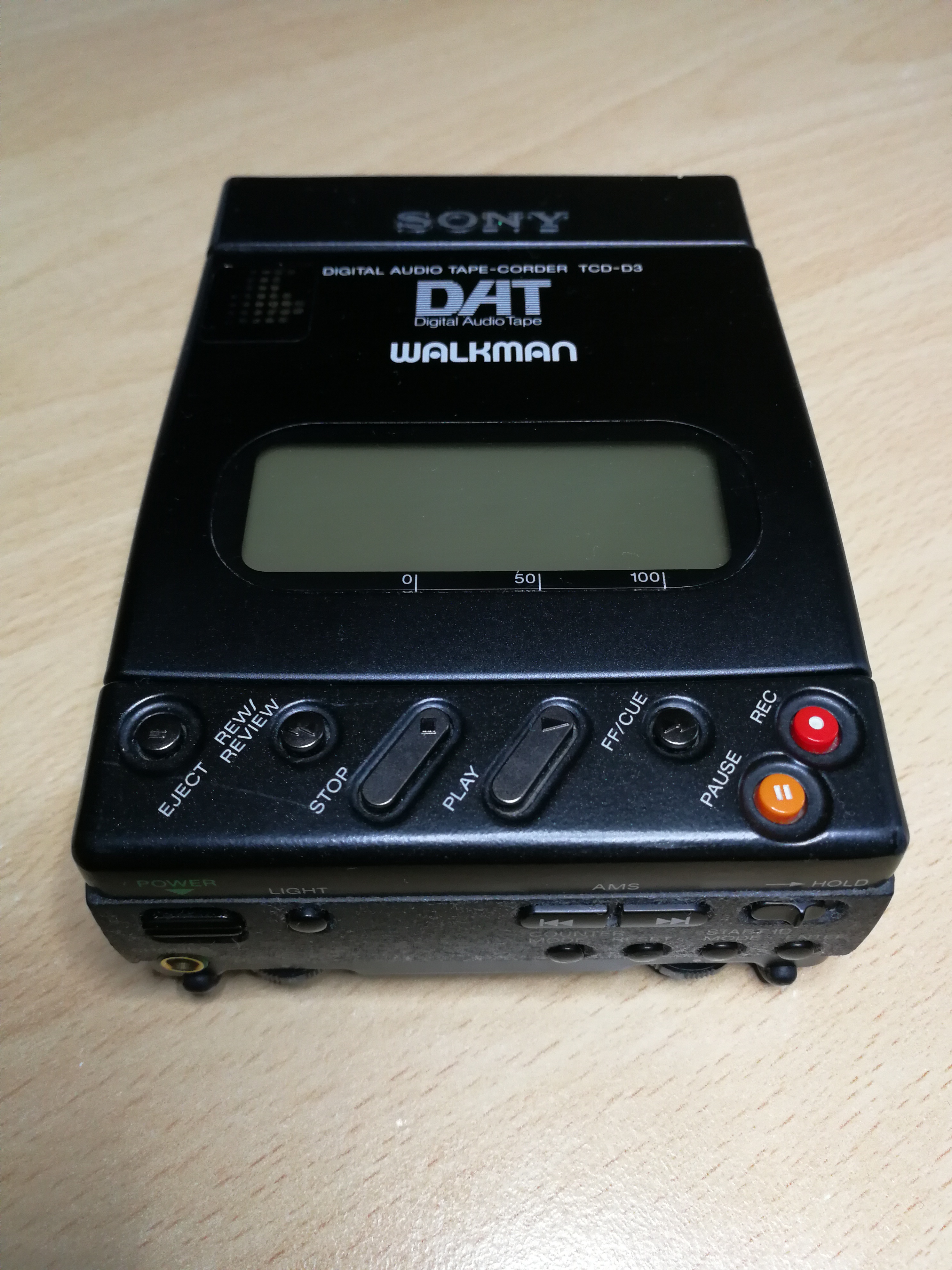
Sony TCD-D3
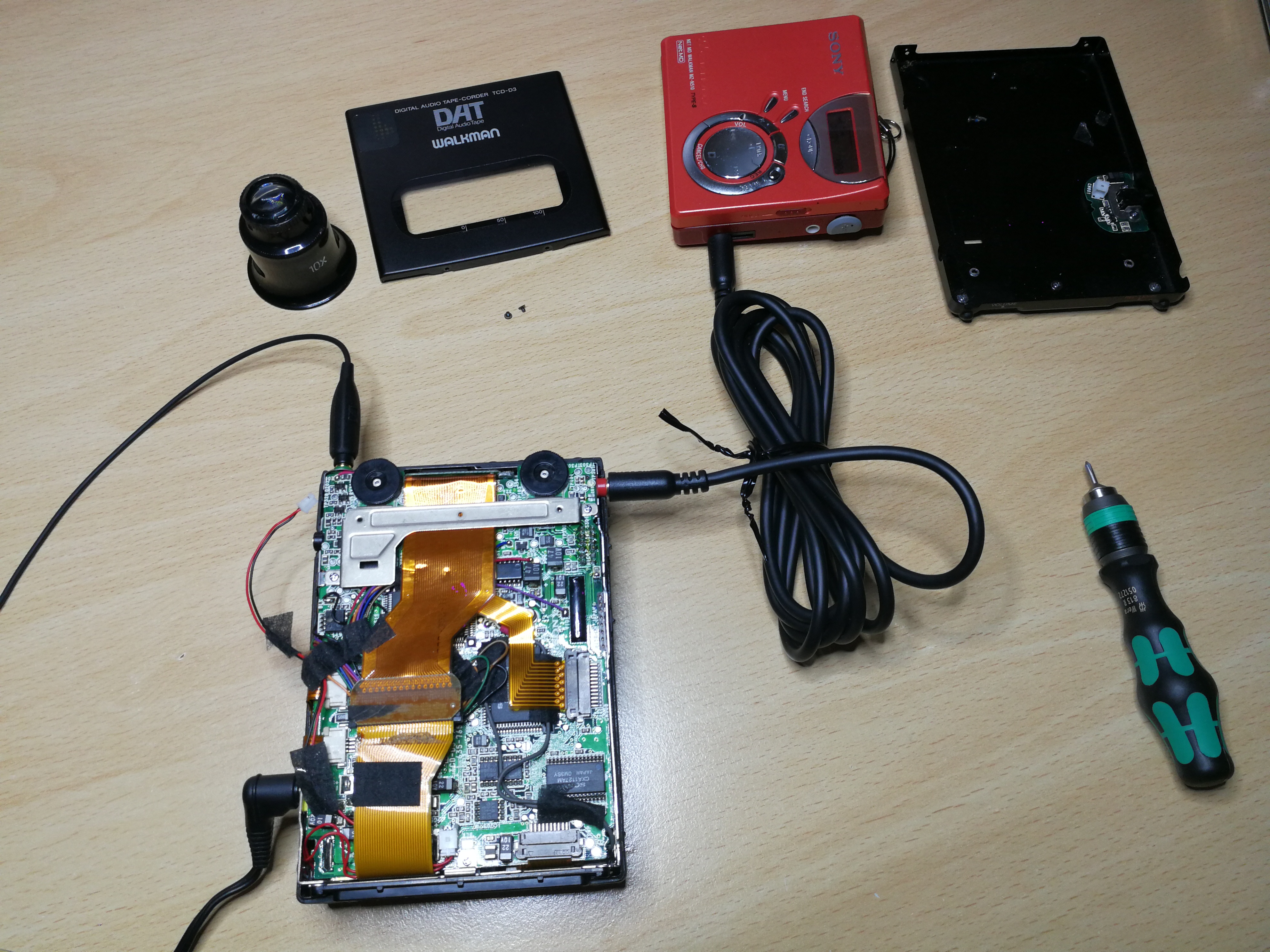
At least one blog post per month to write I have set myself the goal, even if it is not always easy to implement this temporally. Anyone who has small children himself can perhaps imagine that. But in the evening and in between, I can collect material and edit it. -> it just takes everything much longer. This time I organized a Sony DAT recorder for retro audio. It is a Sony TCD-D3 from 1990-91, a so-called DAT Walkman.
DAT (Digital Audio Tape) is an audio magnetic tape recorded digitally. The recording format and the sound quality are essentially similar to those of the audio CD. The recording takes place on small cassettes, which were also used in the storage area in the EDP (DDS tapes). The DAT format was intended as the successor of the audio cassette, could not prevail in the broad market. It is also discussed here that the music industry did not want to see the format in the consumer world, as it was possible with the system to produce digital, lossless copies.
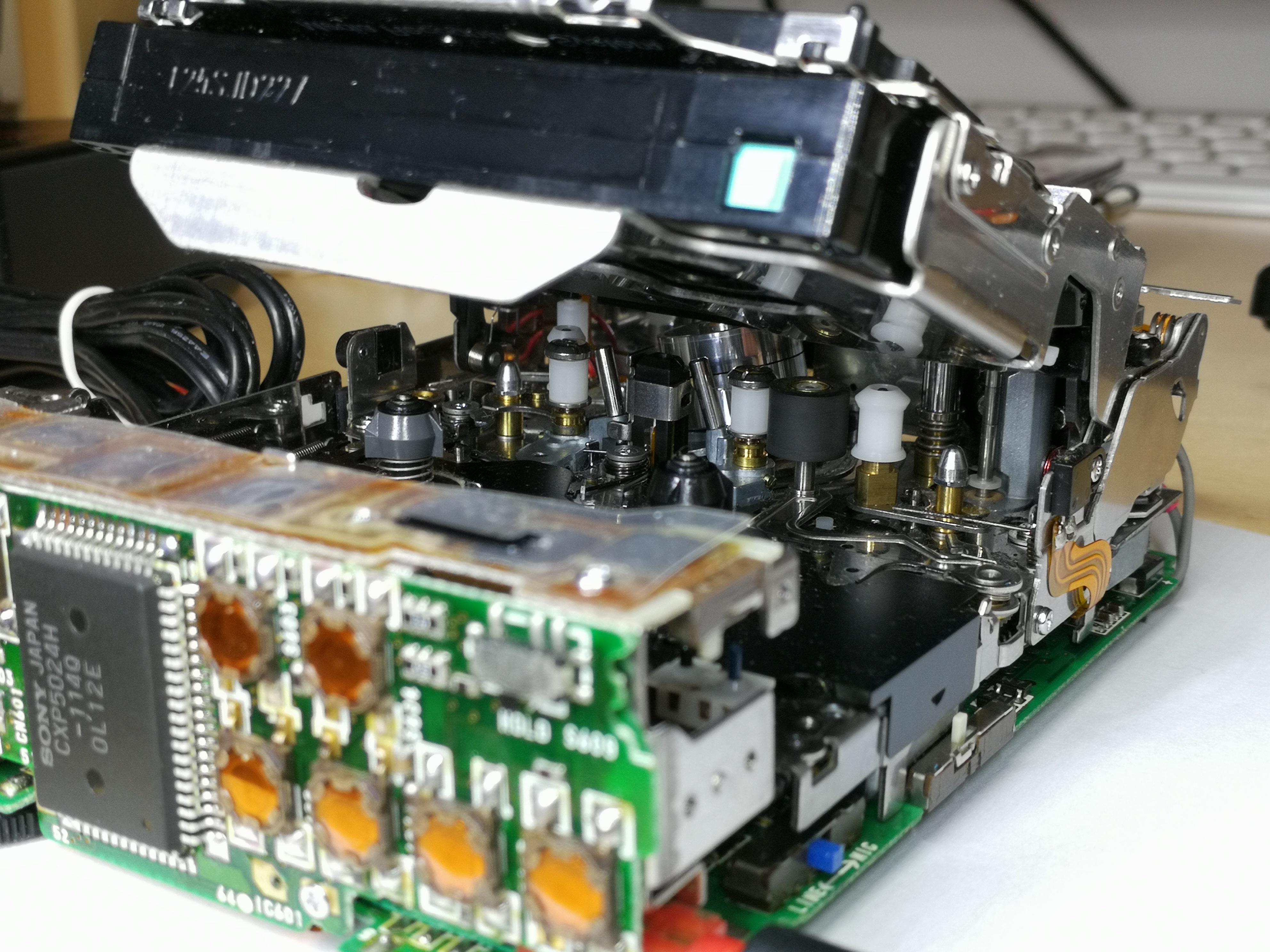
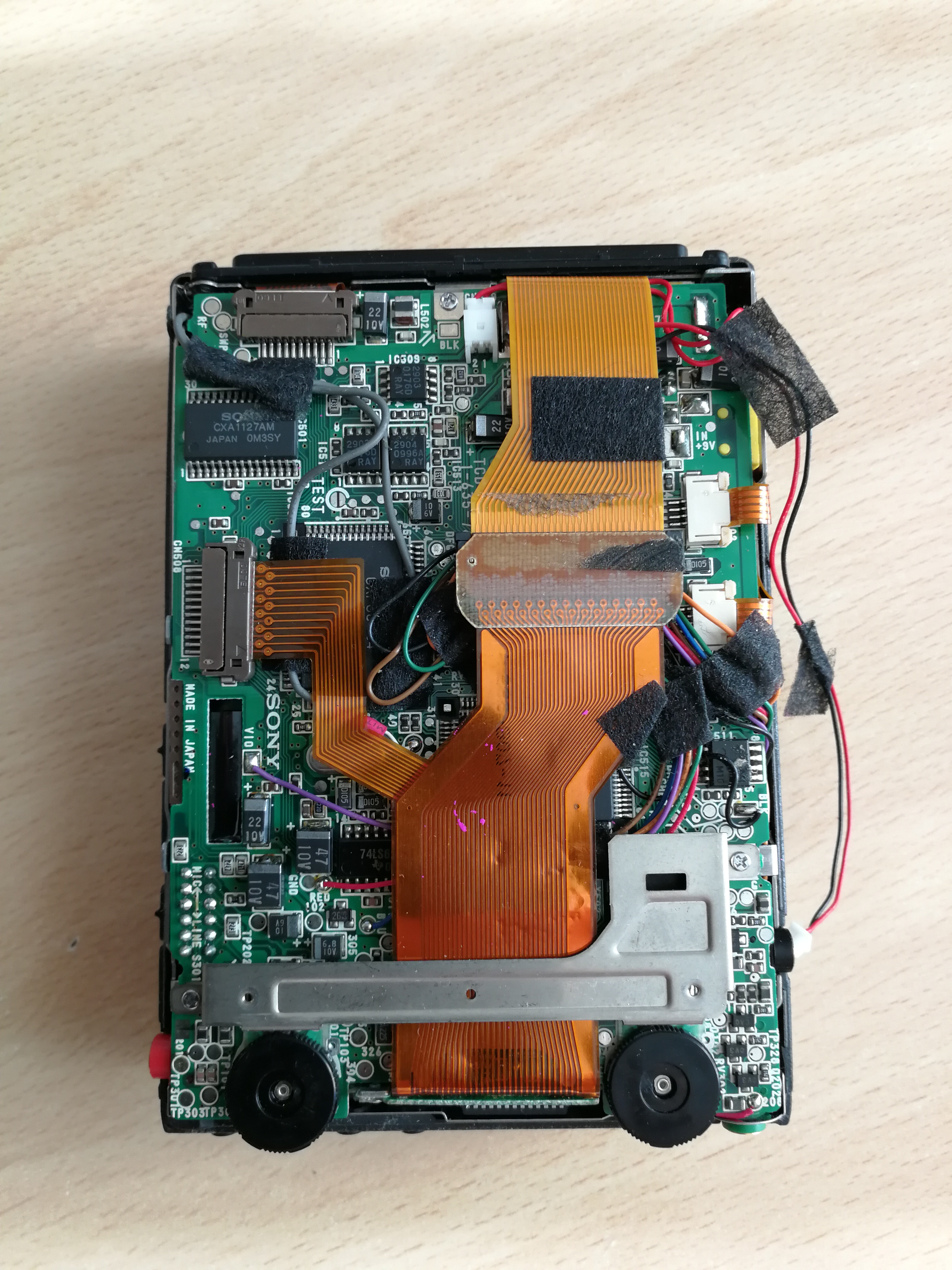
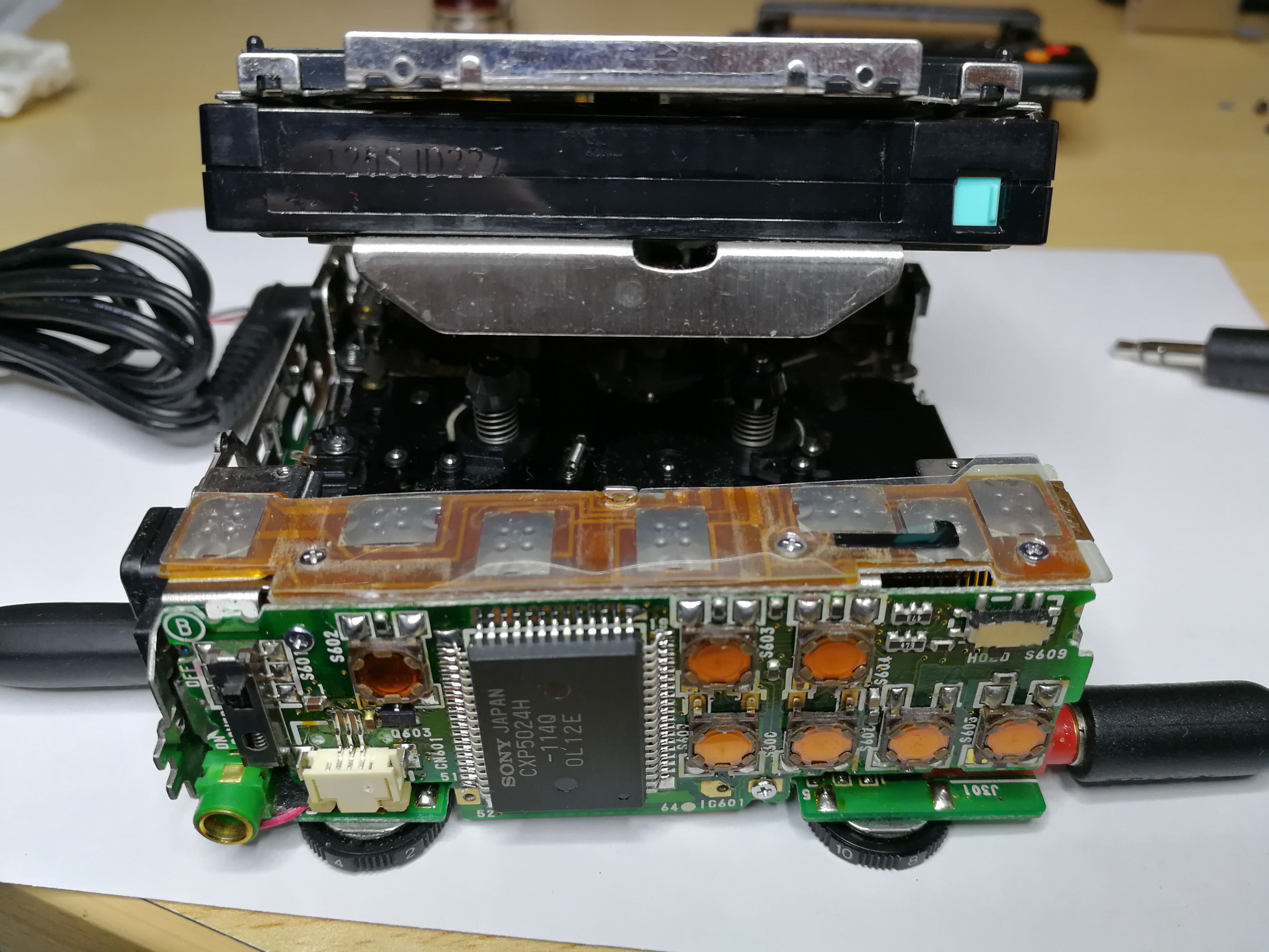
The technical structure of the cassette drive corresponds to that of a video recorder. The tape is pulled out of the cassette with loading arms and passed around a rotating head (DAT-R). The recording is done in helical scan. The copy, which I acquired this time as “defective”, was with the defect: Cassette shaft does not open, described. After dismantling, I noticed that I was not the first to look at the inside of the device after the factory. Someone was already messing around. All (tantalum) capacitors were soldered, the lead wires to the battery pole contacts were “pinched off” and the wires were missing. The Flexiprint, which connects the front panel to the mainboard, had a broken track when looked at closely.
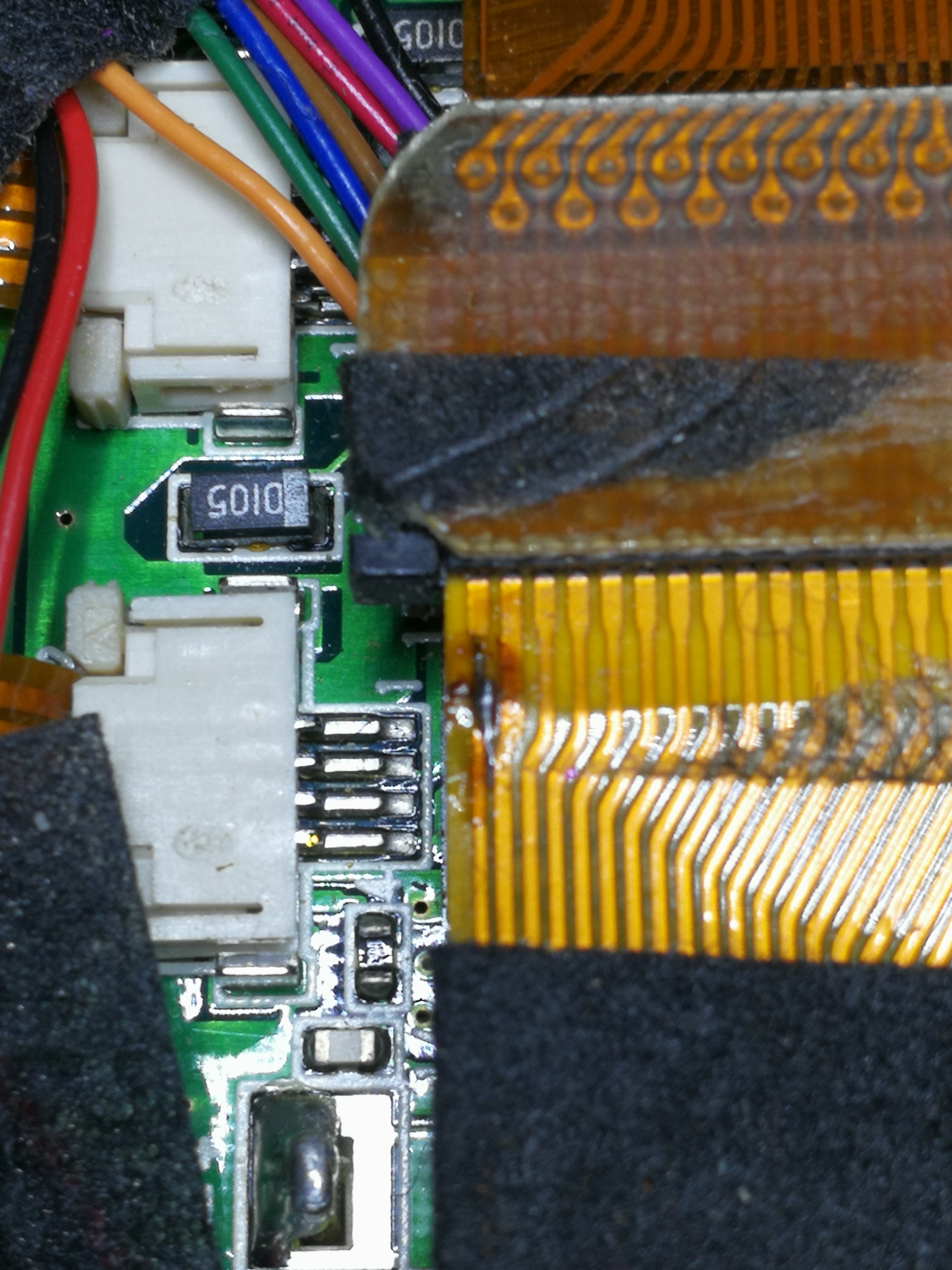
fixed trace
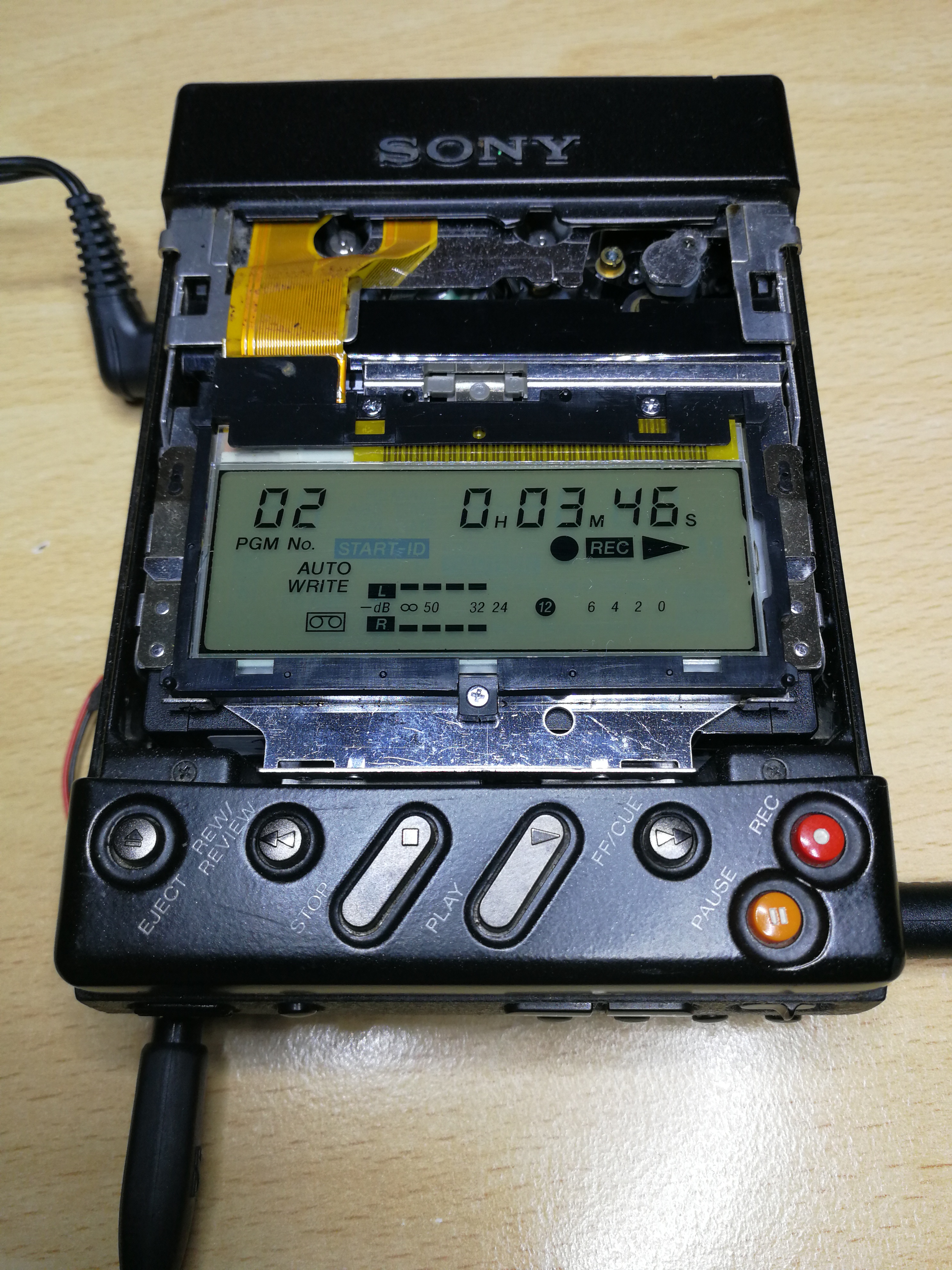
The broken wire could be repaired by carefully scraping off the insulation and brazing a stranded wire. The capacitors I have all newly soldered and of course checked before. Here I noticed that some were not soldered properly and had a cold loosening at a pole or were not connected to the pad. The battery contacts were also provided with new wires. On the mainboard there is also a DC / DC converter, which makes the supply voltages for the logic and the audio components from the 9V input voltage. (5V +/- 7V). This converter is housed in a completely soldered tinplate box. Of course, nobody was inside and checked the Elkos inside. That was done quite quickly and the small box was overtaken. Now I was able to provisionally reassemble the boards and drive and put them into operation. As data carrier I used a DDS (storage) cassette. So tension on it and “Eject” pressed and lo and behold, the cassette compartment opens immediately. From my Handyaudioplayer as a music source, I made a trial recording. And what can I say, a wonderful sound quality!
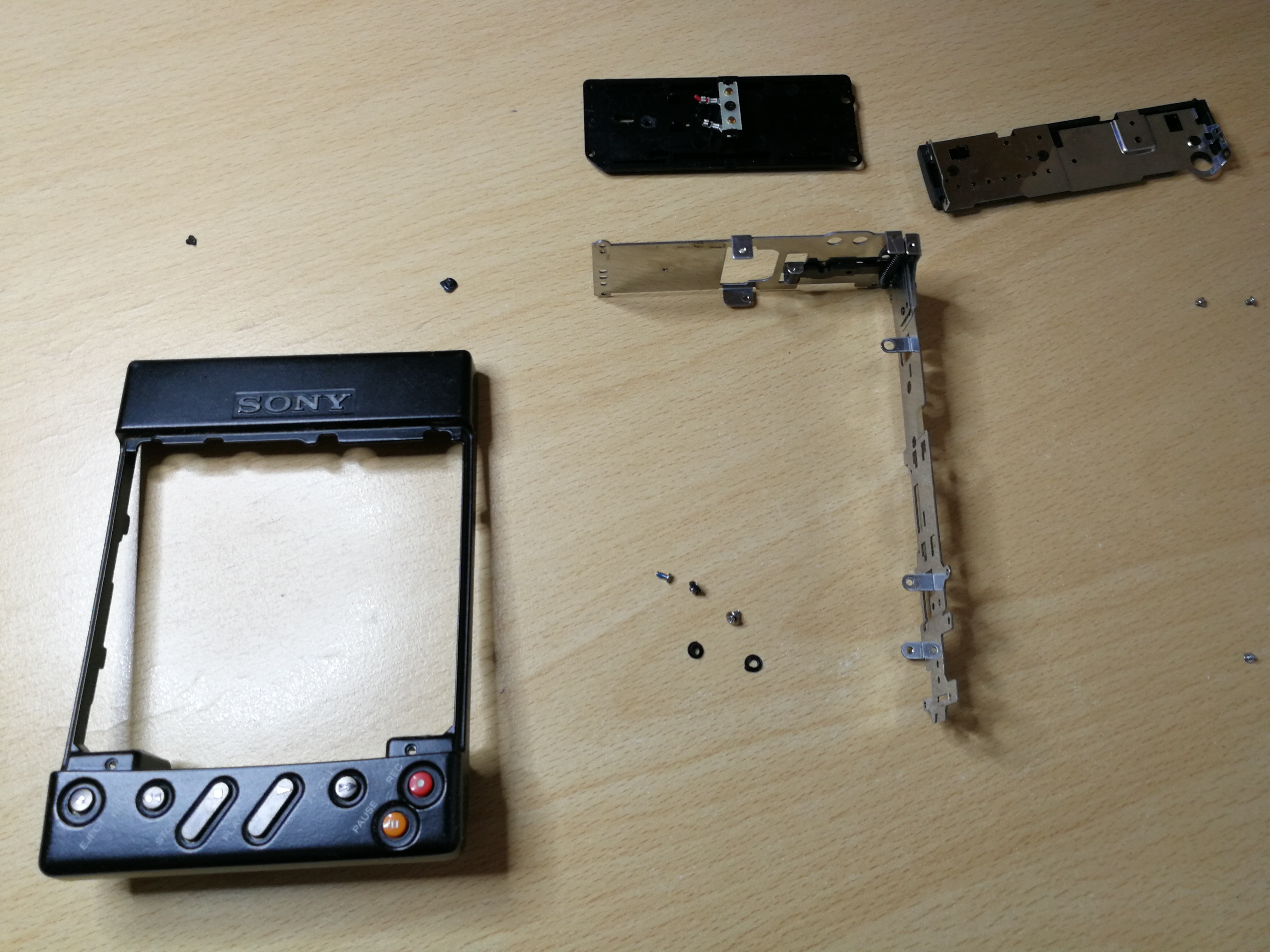
The next issue to fix is more of a visual nature. These are the side casings, which are coated with a rubber coating and this begins to seem to change chemically and becomes sticky. So I washed this gum carefully with isopropanol and tried not to replace the white printed lettering with. That worked quite well. With acrylic clearcoat I then painted the parts.

painted side casings
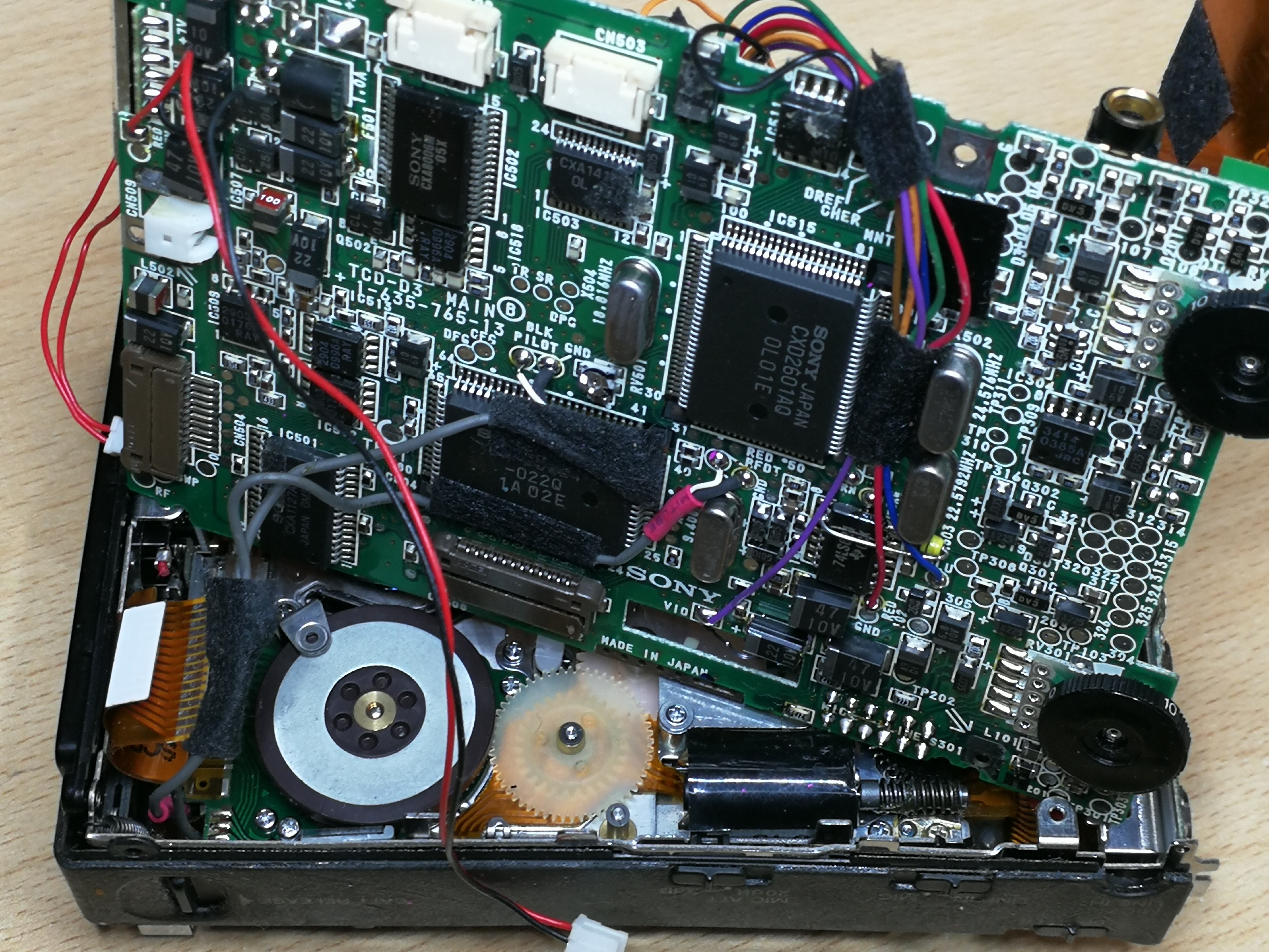
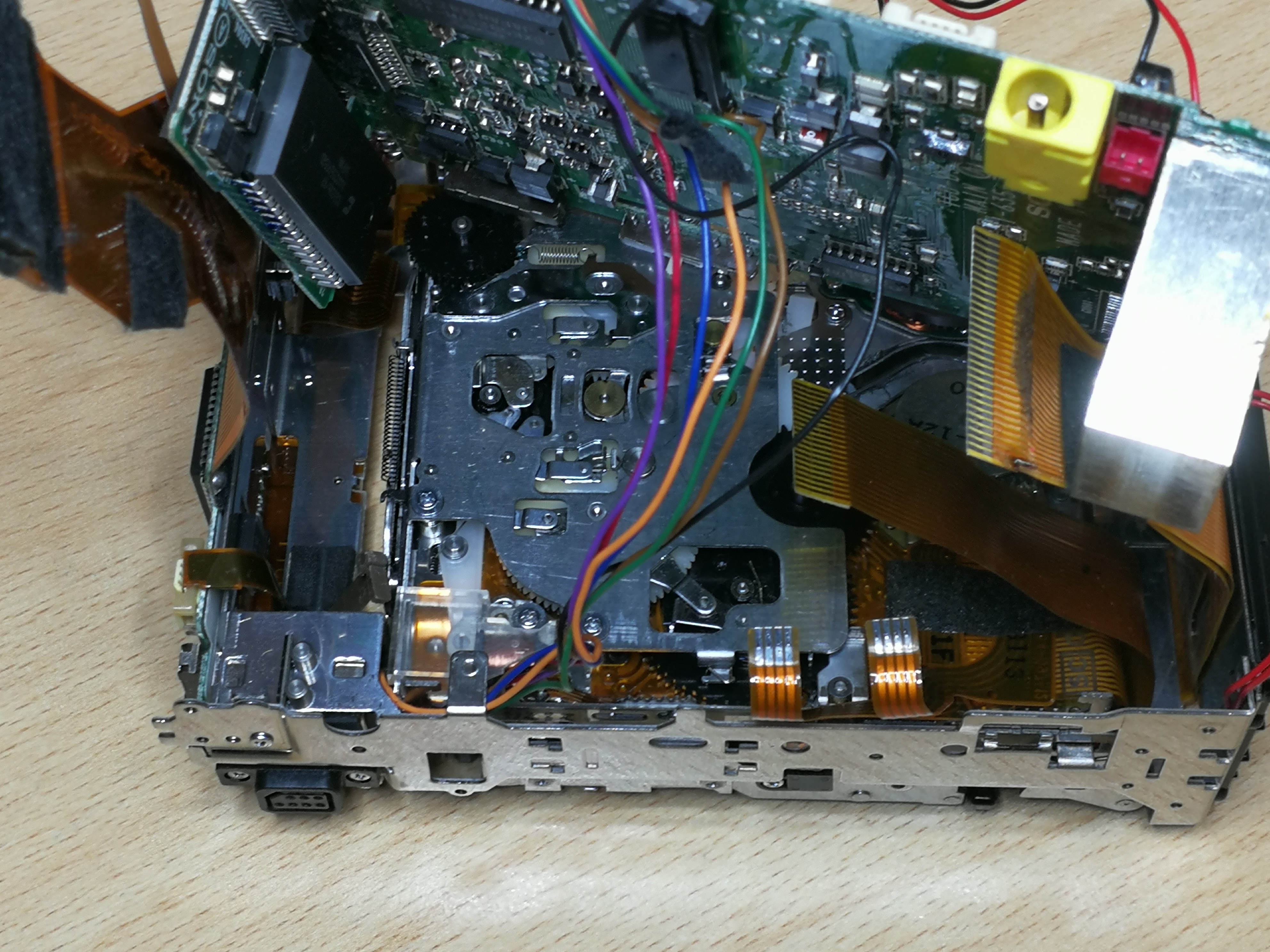
After curing the clearcoat I was able to assemble everything again and start the final test. The following pictures show the inside of the TCD-D3.


Specifications of the TCD-D3
- Type: Digital Audio Tape Dec
- Audiotracks : 2-channel stereo
- Tape speed: 4.075, 8.15 mm/s
- recording time: 240 minutes
- headsystem: 2000rpm, rotary
- D/A converter: 16 bit linear
- A/D converter: 16 bit linear
- Samplefrequency: 32-48kHz
- Frequency Response: 20Hz to 22kHz
- Signal to Noise Ratio: 90dB
- Dynamic Range: 90dB
- Total Harmonic Distortion: 0.0008%
- Analoginput: 80mV (line), 0.25mV (mic)
- Analogoutput: 0.5V (line)
- Dimensions: 85.2 x 40 x 120.1mm
- Weight: 0.42kg


One Response
Hello, I have just acquired a TCD-D3, at the moment it does not power on. I’ve not opened the unit yet, I believe it has an internal fuse, which is listed in the service manual, but I cannot find it on the schematic. I’ve studied your photos but cannot see it, any idea where it is? I was also wondering what to do with the sticky sides, good to read that the coating can be cleaned off without losing the lettering.