Geiger counter and radioactivity

Loading

One project that had long been of interest to me was the detection of radioactive radiation. After the horrible powerplant accidents in Japan, this idea was recalled. I could still vaguely remember owning an unused counter tube somewhere in my old workshop cellar. – After some search it turned up :). Thanks to the Internet and the search engines, a data sheet was also found quickly. The counter tube is a ZP1400. A self-extinguishing Geiger-Müller counter tube with mica window. The tube is according to data sheet with neon and argon filled as quenching gas. The operating voltage is 400 to 600V. The capacity between anode and cathode is about 2pF. With these and other information from the data sheet i now can tinker a circuit to take the tube in operation. I have used this small project to introduce our apprentice to the board layout at the same time and to get acquainted with the creation of small programs on the Arduino Uno microcontroller board. In this post I introduce only the “old-fashioned” circuit, where only the impact of ionizing radiation is made audible to the count wire. (the typical crackling). This circuit then provided the basis for the apprentice to realize the count of the pulses with the microcontroller and to visualize it on a two-line LCD.
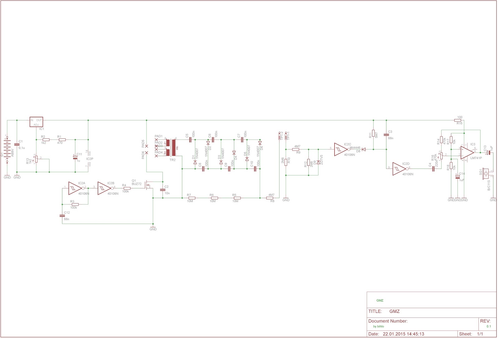
Wiring diagram with high voltage supply and pulse amplifier

Using the well-known layout software Eagle, I have drawn a circuit in which the high voltage is again generated by a switched transformer and subsequent Greinacher cascade. The control takes over this time no 555er, but simply a feedback Schmitt trigger. The time base is set via the coupling resistor and the capacitor. Thus, the high voltage is available for the counter tube. In order to be able to count the impulses, two factors are ensured. The impulse must not exceed a certain height. (Otherwise the following electronics may die) and the pulses should be audible (boosted). So the peaks are limited with a zener diode circuit and put into a “nice” shape with Schmitt triggers and then led to an op amp. At the output of the op-amp then hangs first a small speaker …

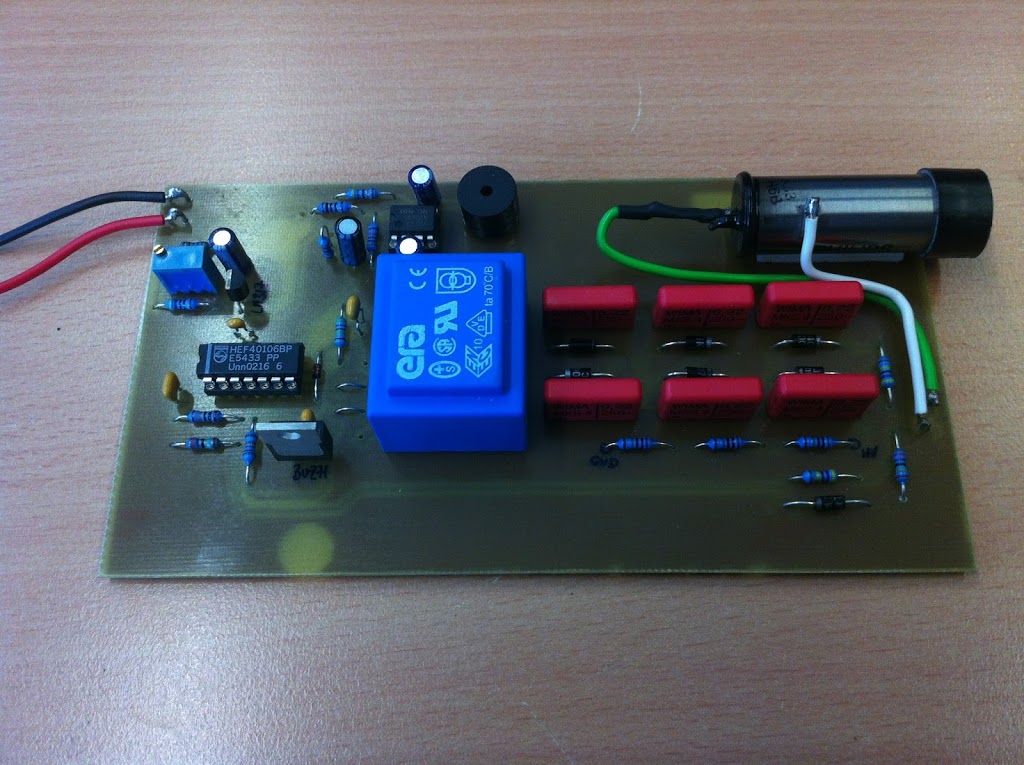
Arrangement of components on the PCB

After the circuit board was etched and assembled, it was time to test. But with what? I needed some weak source. I held all sorts of items in front of the counter, but it did not change much. There was a cracking sound from the speaker four to eight times a minute. So I started researching the net again. And came across the term “radium color”. This is the self-luminous color with which the dials of old watches were painted, in order to be able to read the time even in the dark. This information gave me an idea. From my grandfather i inherited once an altimeter of a WW1 aircraft (manufacturer LUFFT) whose dial might have been painted with that kind of color. So get out of the showcase and held in front of the counter tube … The result can be seen in the video.


The oscilloscope picturetube

Loading

At the beginning of my blog, I talked about a small project with an oscilloscope tube. Since there are still pictures in the archive, I do not want to withhold it from the blog here:

Cathode ray tube with high voltage generation


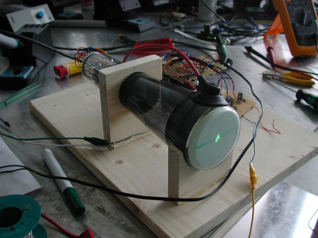
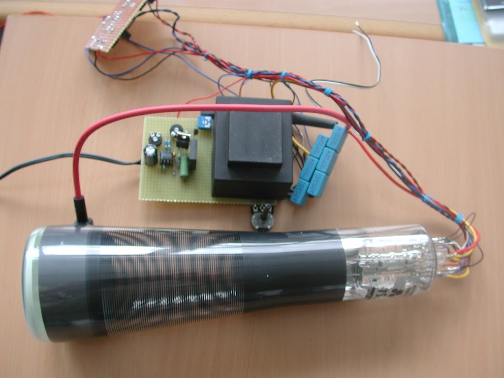
A cathode tube (Braun tube) consists of an evacuated glass bulb in which a hot cathode of tungsten wire is heated by an electric heating wire. The electrons emerge from the surface as a charge cloud (annealing emission). Between the positively charged anode and the hot cathode there is an electric field in which the electrons are accelerated. A pinhole allows the approaching electrons to pass only a bundle of determinable diameter, the actual electron beam. The electron beam can then be further accelerated.
The Braun tube – as it is e.g. is present in a cathode ray oscilloscope – has two capacitor plates each to deflect the electron beam. (X and Y baffles). The tube is a Philips B7S 401 oscilloscope tube. For the sake of completeness, I list some technical data here:
  • Indirectly heated cathode, heating voltage Uf = 6,3V
  • Heating current If = 90mA 
  • time for heating kathode tK =1min
  • total accelerationvoltage Ua= 1,2kV
  • Base point tension of the post-acceleration resistance Ug5 = 300V 
  • acceleration voltage Ug4 = 300
  • focusing deltaUg3 = 20V … 50V
  • pre acceleration volatage Ug2 = 1,2kV
  • reverse voltage Ug1 = -30V … -80V
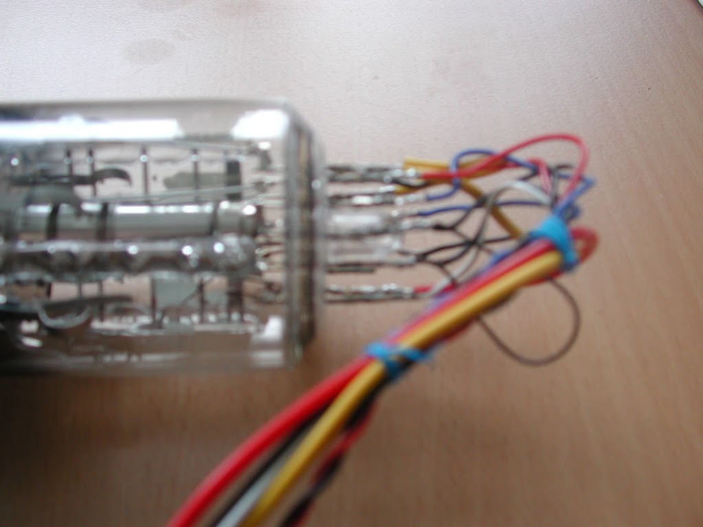
Connections on the tube socket

The aim of the project was therefore to put the small tube back into operation and to lure her a few pictures. So a drive had to be built. Since the supply voltages are quite varied (6.3V to 1200V), this problem had to be solved first. With a NE555, a few components and an old transformer (240 / 12V) a high-voltage power supply was tinkered.
The principle is simple: A DC voltage is switched on and off very quickly with a small circuit. This switched DC voltage in turn connects with a power transistor, the output side of the transformer. (ie where normally the 12V are applied now fed) The ratio of the transformer works in the other direction :). So arise at the exit ever a few hundred volts. (depending on the switching frequency). In order to produce over 1200V, I have connected a cascade (capacitors and diodes). (Functionality)
So now all voltages necessary for the operation of the tube are available to produce an electron beam. With the aid of adjustable voltage dividers, the beam current and the grids for brightness and image focus can be set.

the fist illuminated spot

The voltages for the baffles are also taken from the high voltage supply and controlled by transistors. Thus, a deflection of the electron beam in both axes is possible.

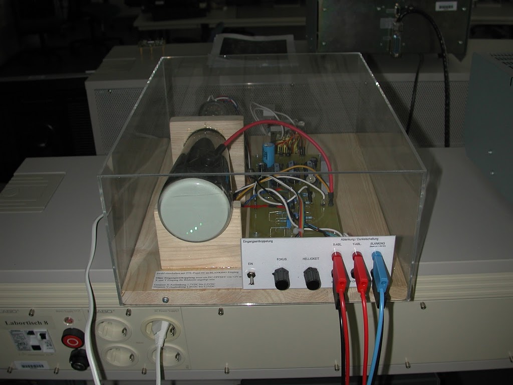
Plexiglas housing

The transistors in turn are controlled by a small pre-stage, which is fed externally with a voltage of -5V to + 5V – the control voltage for the deflection of the light spot. This control voltage input exists for both axes. I added another input to switch the electron beam to “bare”, ie dark. For this purpose, a corresponding voltage is applied to the corresponding grid, which previously block the electron current to the anode.

connections

Thus, the tube can now be controlled directly from the outside, for example, by means of analog outputs of microcontrollers (Arduino, PIC, etc.) or NI DAQ cards with the extra-low voltages available there. After the first positive test runs with the breadboard electronics I then constructed a clean board and mounted the whole construction on a wooden board and covered with a transparent Plexiglas housing.
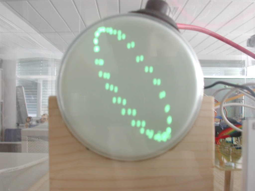
All connections are routed via banana sockets to the outside. For example, you can easily draw Lissajous figures on the screen …

Lissajous-figure done withe NI-DAQ

F101 Voodoo Radarmonitor

Loading

From a McDonnel F101 Voodoo came the following sample that I got from a customer back then, with a request to try to bring it back to life somehow.
The thing I’m writing about was a black cylinder about 30 centimeters long and about 20 centimeters across. On one end face of the cylinder was a picture surface as seen from an oscilloscope, with a rotatable scale ring with a 0 to 360 degrees angle label.
The customer told me it was the cockpit radar of a Starfighter jet. Then I began to research what turned out to be relatively expensive at that time, in the mid-90s, especially since the Internet did not yet exist in the form and diversity as it exists today.

picsource: Wikipedia

But at least I found out that the part was really the board monitor of the radar system of an airplane. Namely to the radar monitor of a McDonnel F101.
A twin-engine fighter aircraft of the 50s cold war US Air Force.
In any case, the part came from this plane – wherever the customer had it from. And he asked me if I had any chance of getting it up and running. He meant that he wanted to see the famous, rotating light stroke on the screen.
At that time, I could not find any information or documentation on the part, how to connect the tangle of cables over cables, which came out of the device …

 
frontview of the monitor

So I started dismantling. Several miniature electron tubes, transformers and many smaller tubes with bobbins with immersion cores and many, many capacitors were installed. In the longitudinal axis of the device, the picture tube was housed, with the magnetic deflection was rotatably mounted about the axis of the tube. Say, the complete deflection unit was turned around the tube by means of an electric motor drive.

topview

Since I had no chance to somehow understand the circuit, especially since apparently some components, such as the entire voltage and signal conditioning were not integrated in the monitor, but apparently were installed elsewhere in the plane, so I set out to dismantle everything. All that was left was the picture tube with the mechanics and the deflection coils and the drive. On a breadboard I started to make my own drive for the coil drive. For the deflection coil itself, I built a sawtooth generator with a sufficiently strong power output stage. And for the high voltage of the tube had to serve an old line transformer of a television, which was driven by a NE555 (the old known timer module) and a matching power transistor (some BU508 …).

and it´s turning again

The whole circuit was operated at about 24V and took over 2A. (including cathode heater and electric motor and the scale bulbs that illuminated the labels).
But it worked. On the screen was a green line, which turned at the adjustable rotational speed. That was already everything. There was no beam modulation or the like to draw any simulated radar images. Today you could work together with small microcontrollers like Arduino and co, quite simply …

The Stirling engine

Loading


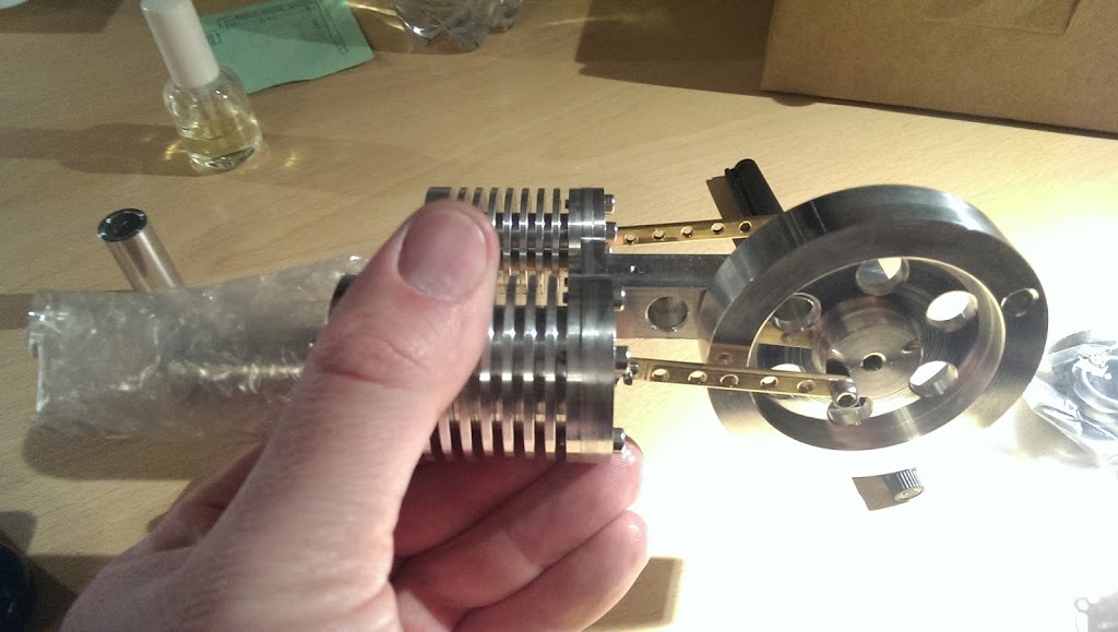
the finished machine

As a gift I received in the winter of 2014 a kit for a model of a Stirling hot air machine. The design plans, as well as the largely prefabricated parts, come from Mr. Klaus Künneth, the operator of the website www.kk-stirlingmotor.de

To build and install only a little manual skill and a few gauges and tools are needed. (Stand drill, drill and tap, a grinding block with polishing wheels, at least a sliding calliper, a little clear coat and machine oil). On some parts holes of various diameters are to be made. For example, on the flywheel, the connecting rods. In the cylinder and head cover, the mounting holes are to drill and thread to cut.

drill the flywheel

After preparing all the items, everything is polished to a high gloss on the polishing machine. Then you can start with the assembly. All in all, one should take a few hours to have the model beautiful, meticulous and functional. From a few parts is then also quickly made a small spirit burner, which provides the necessary heat for operation under the working piston. Everything together is then mounted on the clear lacquer-sealed wooden base plate.

finished polished unit
The functioning of the Stirling engine is described by Mr. Künneth on his website as follows:
 
“The Stirling engine is also called a hot air engine and is a heat engine in which a closed working gas such as air (in this case) or helium is alternately heated and cooled from outside at two different areas (hot side and cold side) to generate mechanical energy. The Stirling engine works on the principle of a closed cycle and is an example of the energy conversion of a poorly usable form of energy (thermal energy) in the better usable form of energy of mechanical energy. The Stirling engine can be operated with any external source of heat (or cold) (solar, wood, gas, liquid fuels, in this model with spirit).”
 
short video link:


The old repair shop

Loading

While browsing the digital archives, I noticed the following pictures again.
Meanwhile, more than ten years have passed since I had to initiate the end of the television repair shop.

Look in the old workshop

Almost at the same time as the widespread use of flat screen televisions, orders were down. Except for a few customers, who insisted on retaining the old technology from ideational values, hardly anyone could fix it. Due to wage side costs and realistic, minimal profit-oriented pricing, it was just too expensive for people. If, for example, a repair of the high-voltage power supply of a television (replacement of line transformer, driver transisor and various capacitors and resistors) a price of about 90 euros assumed, that was again borderline, almost too expensive. If one considers that for these sum the parts scarcely 40 euro in the EK cost, then for the remaining 50 euro the error had to be searched for and found, everything to be expanded and reinstalled.

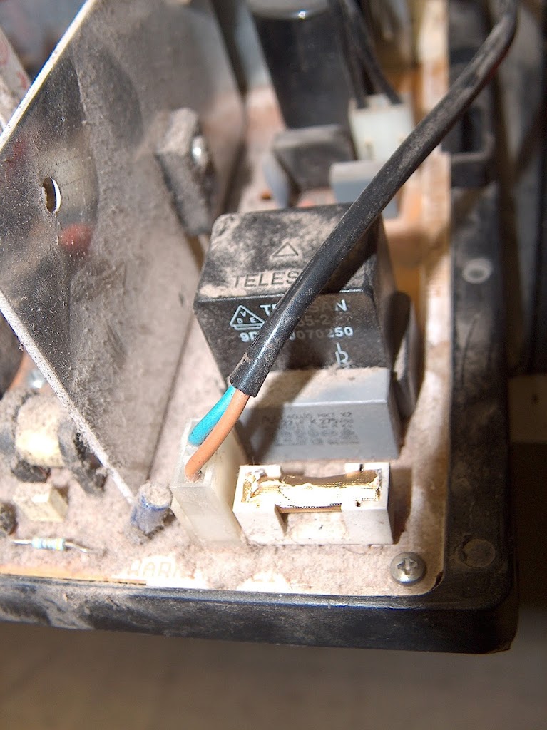
The unit had to be cleaned inside (often we got “boxes that collected the dust and nicotine of twenty years”.) Also, a careful test run should be done, so what about the 50 bugs? Hired labor costs more than half of non-wage labor costs. How many devices do you have to repair during the day in order to cover your costs?
 
 
dust accumulation

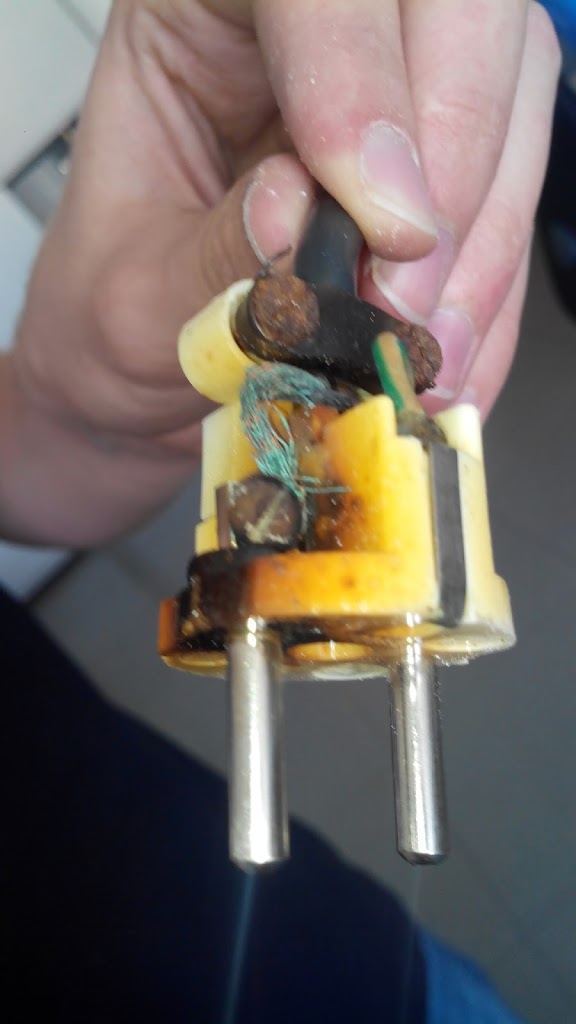
Sometimes you could see curiosities. Since one or the other owner of the TV has ever tried even as a repairer and found a faulty network backup. – “No problem, is only a backup …” Which is then wrapped in the absence of a suitable new backup and knowledge simply with cigarette paper …


“expert” repair of the customer
 
“Then it works again …” which turns out to be not quite correct. After inserting “it pops and flashes” and nothing was more … So the device came to me on the desk … “Why is the repair so expensive? – was only a fuse broken – I know myself out there – I am an electrician “You can hear such sayings then.

The 80s and the Watchman

Loading

In 1985, the company Sony brings a small, compact and above all mobile TV on the market. The Watchman Voyager FD20-AEB. It has been designed to be used everywhere. For example, in the car, on vacation, just everywhere.
It is not a TV with LC display, or TFT, or LED display. No. The TV brings the image by means of a cathode ray tube (Braun tube) to the eye of the beholder. And not in the brilliant color variety and resolution of today’s receivers, but in black and white (BW).


The screen diagonal of 4.7 cm can be displayed with the help of a clip-on magnifier still a little enlarged.
The receiver is a multinorm receiver that covered the European television standards.

It was tuned manually by means of a side-mounted “rotary wheel”. The reception tapes VHF / UHF can be selected with a slide switch. Of course, only analog TV reception is possible.

source drawing: Frank’s Taschenfernseher.de


Settings such as brightness, contrast and also the image capture can be carried out on the underside of the device.

 Tunermodule and flattube

The power supply comes from four 1.5 volt AA batteries or from a power supply. At a power consumption of 2 watts is relatively fast on battery operation. The high voltage generation and heating of the flat screen tube is probably one of the biggest consumers of electricity.

The structure of the boards is very discreet. There are hardly any integrated circuits. The large tuner module can be seen on the left in the picture. The supply of signals takes place exclusively via a telescopic rod antenna. A built-in speaker provides the sound. Optionally, a jack for connecting a headphone is installed.

today there is only more noise to be received

before Gameboy and Playstation

Loading

 
A trend of the 80’s were  mobile video games. As in the Gameboy, PSP and in the meantime also smartphone times, it was quite practical to have a small, compact game console with you as a young person.

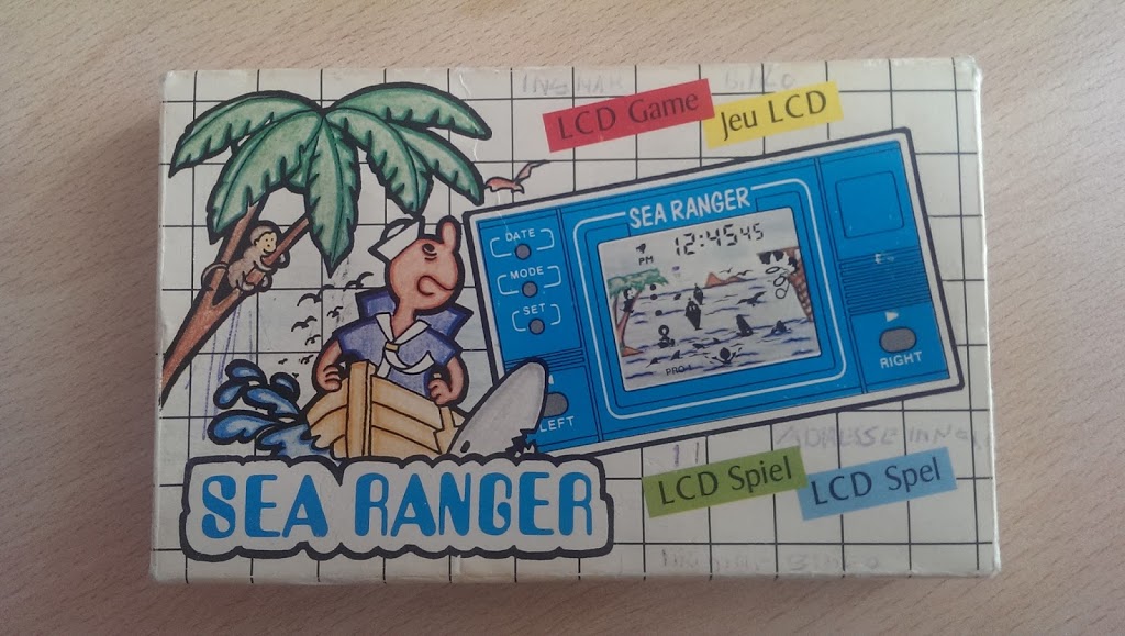
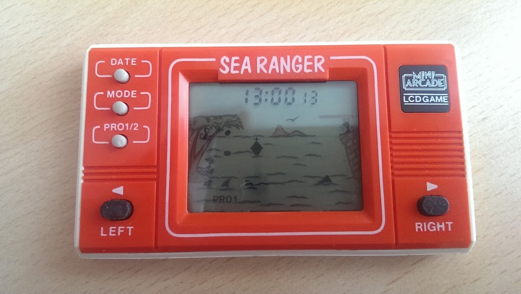
As an example, I dug up one of these “mini consoles”. It is a popular video game called “Trick o Tronic” with a small LCD screen. The difference to today’s LCD displays is that the game image does not consist of individually controlled pixels, which in total show the game figures, but each figure represented in the image was a kind of controllable symbol, so to speak. So, for example, a male had to run from left to right, so every movement and position was present as a separate symbol.


The background of the field was simply an image (photo or drawing) behind the LCD that represented the scene. The whole game was powered as well as the former digital clocks, with a 1.5 volt button cell. The sound of the game came from a piezo loudspeaker that could play beeps. (but only with one frequency)
 

from Video8 to Digital

Loading


Now, during the holidays, it is a bit of time to copy the time stored on magnetic tape image and sound to new media.

The video recordings of the early 90s were still analogue on 8mm tapes instead. No, not Super8 (that was the movieformat like in cinema those times but much smaller), but on Video8 or HI8 (the better quality variant – comparable to VHS and SVHS, where the “HI” or the “S-” technically by a separate recording of the Y – and C- signal was realized (Y = luminance, so brightness information and C = chrominance, ie color information) .The recording itself, took place on magnetic tape in helical-scan technology (as well as VHS, U-Matic, Betamax, BetaCam, Video2000…). Except that the tape just has a width of 8mm and not 1/2 “or 1 inch, as with other systems. Also the sound is recorded in the helical scan.

In order to get the old records into a digital format that is common today, you need the following four things.
First, the tape (cassette) with the probably exciting content of days gone by. Next, a player is needed.

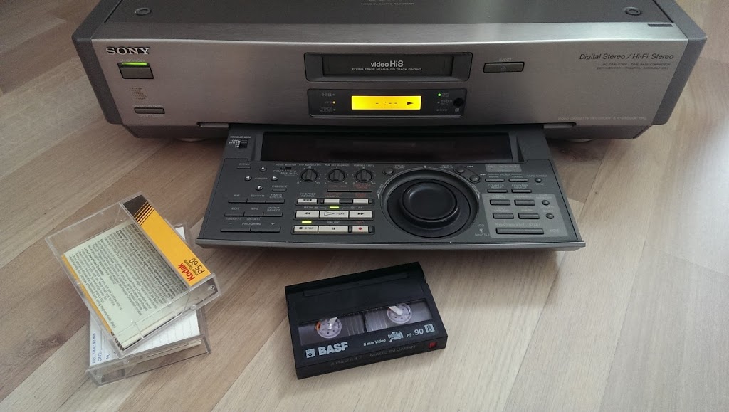
Here I got myself a then professional HI8 recorder, with which the playback of the tapes should work. The recorder is called EV-S9000E from Sony and came back to the net after almost twenty years break. After a short while, the smell of putrid fish was noticeable. An indication that some electrolytic capacitors of the SMD design are no longer in order. (A well-known problem with devices of older age and elko’s smaller, more compact design.) Nevertheless, I left the recorder on the net and made myself smart, which functions failed because of the numerous, not value-accurate components. So the power supply started and delivers at least. The flourescence indicator has failed. The 60V anode voltage seems to be missing here, no matter the tape drive works, so bring the analog signal to the computer.
 
 
For this I got myself a video to USB converter of elgato. Quickly installed the necessary software and inserted the first tape and pressed “Play”. The picture, however, was a disaster. All lines were totally distorted and offset. (As if the line frequency was wrong). So, before I put everything together again and disappear with the recorder in the workshop, I have again seen in the Config menu of the recorder. There I switched all AUTO options to manual, the television standard on PAL geknüppig and last but not least the TBC (TimeBaseCorrector) off. Lo and behold, the TBC is over too. Actually he should generate an absolutely stable time signal for the video line, but with defective electrics this is no longer possible.
Since I do not have ten tapes to digitize, the recorder should hold out …

Amiga – Genlock cable

Loading

Some time ago I wrote a post about the Amiga Genlock “VESONE”. It can be found under the title “Amiga and Genlock”.(link)

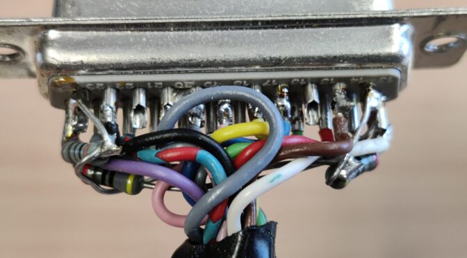
Apparently there are still some people who own such a device and want to use it again. But since, as with me, the necessary cables, software etc. are not necessarily stored where the device is, it can be difficult. I thought to myself that it doesn’t matter, because what is the Internet for – but far from it. You won’t find anything. I noticed that now when a blog visitor asked me about the pinout of the RGB to genlock cable. I didn’t find anything on the net. But deep in the boxes in the cellar in various cable boxes, I was lucky. The cable appeared. In order to share the pin assignment with other retro fans, I have drawn out the pin assignment and put it online here.

So here are the pictures and the pinout (Amiga_VESGenlock_Cable)