Tag Archives: Recap

Sony Walkman WM-DD11

Loading

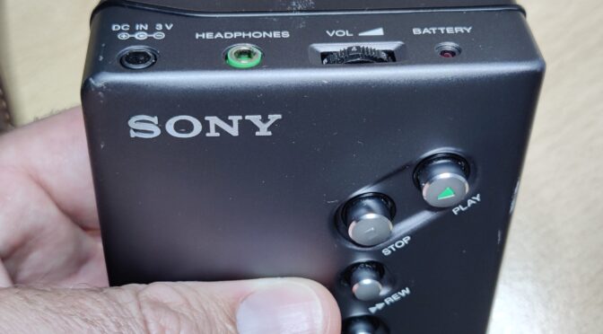
The portable cassette player from the manufacturer SONY with the type designation WM-DD11 is the content of this article. Colloquially known as “Walkman”, I received this part for my collection. Of course with the comment “defective” – ​​so again a little challenge and at the same time the hope that no mechanical, no longer available parts are affected. My request before the purchase whether there was any damage to the circuit board was also answered in the negative. The device is so far in order, the tape of an inserted cassette is moving – there is just no sound from the headphones. So ideal conditions for a restoration.

But unfortunately you cannot trust every statement and you cannot look “under the hood” beforehand and convince yourself whether the actual condition of a device corresponds to the description. When I held the part in my hands, the first impression was also very convincing. There were no noticeable scratches and dents. The area of ​​the battery compartment that was visible from the outside was also clean. So batteries inserted, also an audio cassette and then pressed on play. Lo and behold, the tape transport runs as described. Even as described, the part does not make any sound. So perfect starting conditions for my mini repair / restoration project.

But before I start dismantling, I did a little research on the history of SONY’s DD Walkman series. The first model in the DD series was sold in 1982. The designation “DD” stands for “Disc Drive”, which means that the “Disk”, i.e. the flywheel disk, is also part of the capstan drive system (motor). The belt for the other drives (tape reels) is placed directly around the disk. There are / were two price brackets of the DD models – the DD series with one-digit numbering (DD-1, DD-2, etc.) and those with two-digit numbering (DD-11, …). The devices with the single-digit number belong to the “high-end rail”. The device restored here comes from the “cheap line”. The DD-11 is not so high-quality and is also more simply constructed, but defective devices are available for very little money and are also fairly easy to repair. (The DD-11, for example, does not have a center wheel, an often defective part of the high-end series that is broken due to weak material. What then usually remains are defects in the electronics or on the mechanical side – an aged belt The belt is the same as that already installed in the legendary TPS-L2 Walkman and has the component serial number: SN 3-499-042-99 (this source or number has not been verified) You can also find the belt if you go to “TPS -L2 belt “searches on various online portals.But now enough information on the general part. I experienced a sobering and grounding of my restoration euphoria immediately after unscrewing and opening the case. Unfortunately, the circuit board is not at all undamaged. Once again someone did not remove the 1.5Volt cells and left them in the device for a very, very long time.

The batteries that leaked, as it is, have left clear marks on the circuit board. This means that extensive cleaning of the circuit board is necessary before the search for corroded conductor tracks can begin.

After cleaning and removing the battery electrolyte residues, I was able to make out a few defective conductor tracks. Fortunately, these are pretty easy to fix. In most cases it is sufficient to remove the solder resist in the defective area and to tin the exposed copper tracks. Depending on the width of the track, the defective part of the track is then reconnected with individual strands or wires.

Now the time has come to carry out a first functional test after a provisional assembly. And as described, the capstan drive works, the tape is transported – but there is no noise whatsoever from the connected speakers. Now is the time to look at the number one source of failure – the old electrolytic capacitors. Eleven of these are installed on the board.

When I removed the first electrolytic capacitor for a capacity test, the well-known fishy smell rose again. As expected, the capacitance of the capacitor was also well below the nominal value. So I made a spontaneous decision to remove all eleven electrolytic capacitors in order to swap space. (In modern language it is called “recap”: D)

The following values ​​must be renewed:
– 5 Stück 220 µF / 4V
– 1 Stück 100µF / 4V
– 3 Stück  47µF / 4V
– 1 Stück 10µF / 16V
– 1 Stück 4.7µF / 25V


I like to replace the SMD electrolytic capacitors with SMD multilayer capacitors, as these are now also available in very small designs in high capacities with suitable dielectric strength.

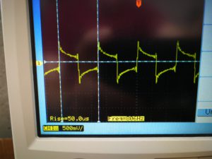
After the renewal, the board looks nice again. A repeated provisional commissioning shows that the effort was worth it. The music on the inserted tape sounds in the expected quality. The next step is to calibrate or adjust the belt speed. A reference tape is required for this. Years ago I recorded one with a very good tape recorder. The recording consists of a 1kHz and a 5kHz sine tone. This band is now used as a reference in the DD11. To do this, the output of the DD11 is connected to a frequency counter or oscilloscope and adjusted with the trimmer potentiometer during playback until the 1000 Hz or 5000 Hz can be seen exactly on the oscilloscope.

The Walkman can now be reassembled. All screws are properly tightened again and finally the function tested again and the beautiful piece can be put in the showcase …
8-Bit Generation: The Sinclair ZX-Spectrum

Loading


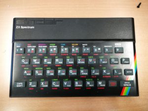
The ZX-Spectrum from SInclair

On April 23, 1982, the Sinclair ZX Spectrum has been marketed by Sinclair Research. [Source: Wikipedia] He was then sold at a price of 140 euros or 194 euros. The two prices refer to the 16kByte version or the 48kByte version. 16kByte and 48kByte are the sizes of the RAM memory with which the computers were equipped. The ZX-Spectrum is the successor to the Sinclair ZX81 and the predecessor of the ZX-Spectrum Plus and Sinclair QL.

The small computer (the dimensions are just 23.5cm * 14.5cm * 3cm) is powered by a Z80A CPU running at 3.5MHz clock speed. The ULA (Uncommitted Logic Array) is the largest chip on the ZX motherboard. She is responsible for the graphics, the audio IOs (for loading and saving programs on tape) and keyboard input. Then there are, depending on the version, the DRAM chips (upper and lower RAM) on the board and another ROM IC, which houses the BASIC interpreter. The small calculator can draw colorful graphics on the screen with a resolution of 256 x 192 pixels and 15 colors. The image output is sent to the antenna input of a TV via a built-in RF modulator. With picture output but I really only the “picture”, because for the sound is not the audio channel of the TV set used. But there is a small speaker on the motherboard, which outputs the sounds of the computer. Which in turn are not generated like in the C64 in a separate chip (SID chip) and that in several voices – no, the MIC / TAPE pin of the ULA is used, which simply switches the speaker via a transistor to 5V. This can then be used to generate simple “beep noises”. Of course, from a current point of view, that’s nothing special at all, but for those who were confronted with it in their childhood, there are certainly some memories associated with it. So also for me. At least then I had the opportunity, with my brother to borrow such a device from a friend. Then of course it was – how can it be otherwise – played. Titles such as “Manic-Miner”, “Ant-Attack” or Flight Simulator were among the most frequently loaded cartridges. Yes – cassettes. At the time it was common to buy the programs on an audio cassette. A simple tape recorder was connected to the ZX-Spectrum via the headphone jack and the LOAD “” keys were entered via the rubber keys on the ZX. Then you had to press on the tape recorder only more play and it could start. The prerequisite was, of course, that the tape speed and the adjusted volume level fit. Only then was the loading of the program successful and the game started. The loading times were from two to often more than ten minutes depending on the program.

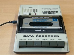
datarecorder for loading and saving from programmcode

In my 8Bit – Retrorechner collection was missing until now the complete series of Sinclair calculator, but finally I could make a bargain and buy a whole set with ZX-Spectrum, joystick module, a data recorder and many original game cassettes. I would like to briefly describe the preparation and restoration of the ZX here. If you get your hands on a computer with an unknown background, which has been lying around in a cellar for the last 30 years, you should not try to put it into operation. If he is not already, that could be his death. Because, as always, there are some parts that can age and change their parameters. Someone could have tinkered with it before to repair or retool something. In this case, the case was dusty and dirty, but there were no missing screws, dents or externally apparent retrofits, such as buttons or plugs. So I could solve the case screws.

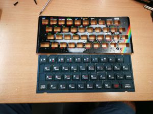
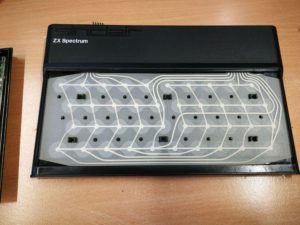
The keyboard foil was quickly pulled out of the clamping bushes and the lid with the rubber keys removed. Now the inner life of the Spectrum revealed itself – and what can I say – 1A. Everything in original condition. No repairs or tinkering have been done on the device yet. So I first started cleaning the body parts. The keyboard is easy to disassemble. In this revision of the spectrum (ISSUE 4A), the metal sheet that holds the rubber mat in the housing is fixed with four “brass bending tabs”. These can be easily bent back and remove the sheet.

Frontblech und Gummitastenmatte enfernt
freigelegte Tastaturfolie

The housing parts were now very easy to clean. I rinsed it with soap under lukewarm water. Also, the residue between the rubber mat buttons could be easily removed. While the parts were now set aside to dry, I dedicated myself to the motherboard.

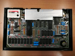
Mainboard des ZX-Spectrum 48K Issue 4A

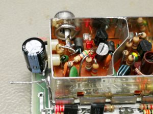
Here all solder joints were clean, no traces of foreign intervention and all parts still in original condition. So I could start directly with the first exams. An ohmmeter was used to test for short circuits in the power supply area. If you look at the circuit diagrams of the spectrum, you can quickly see that the computer is supplied with an input voltage of DC9V. Here the assignment of the power supply socket is to be considered. Here, the plus pole is not the inner pin but the outer ring of the connector. This is especially important if the original power supply is no longer available and you take a replacement. The further structure of the supply concept is as follows: From the 9VDC the + 5V supply is made via a linear regulator 7805. Using a DC / DC converter circuit consisting essentially of the components TR4 and TR5 and a small transformer (cylindrical coil with two windings), a 12VDC and further a -5VDC power supply are generated. Special attention should be paid to this area, as a wrong or missing power supply can damage other components (especially the DRAM ICs). To do this, use a diode tester to test the transistors for their conduction and blocking behavior of the PN junctions. The easiest way to test the small transformer is to use the ohmmeter for low-resistance behavior of the respective winding and high-resistance behavior between the primary and secondary windings. If everything is alright here, one tests the output of each of the three voltage sources with respect to the ground 0V potential. Here are the following guidelines to measure:

  • Eingang des Linearreglers (9V) gegen GND -> ca. 100k-150k
  • Ausgang des Linearregler (+5V) gegen GND oder an Pin9 des RAM ICs -> ca. 300 – 500 Ohm
  • Pin1 des RAM ICs (-5V) gegen GND -> ca. 300 Ohm (im 400Ohm Messbereich)
  • Pin8 des RAM ICs (12V) gegen GND -> ca. 2.6k bis 2.8kOhm
Elektrolytkondensatoren erneuern

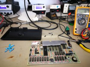
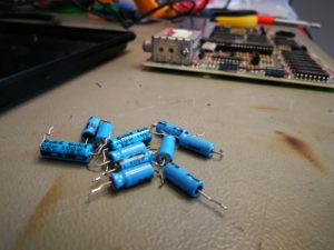
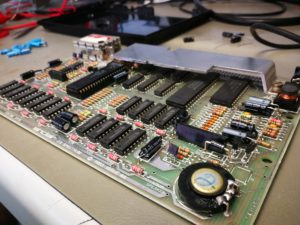
In the next step, the over 30 years old axial electrolytic capacitors are exchanged. This is a pure precaution, because as everyone knows, these parts like to change their values ​​with increasing aging or run out. And what leaked electrolytes can do so everything, I have already shown in older posts. In order to allow the ZX a longer life again, all Elkos are exchanged.

die alten Elkos
Mainboard mit neuen radialen Elkos

Once this work is done, then the exciting part begins. The power supply is switched on. It is best to supply the ZX with a laboratory power supply with adjustable current limit. He may take after switching on not more than 750mA at 9VDC. If that also fits, the voltages can be measured (best on one of the lower RAM ICs). It should be measured at PIN1 -5V, at PIN9 + 5V and at PIN8 12V.

Conversion of the RF modulator to video output

In order to be able to connect the ZX-Spectrum to a display unit, there is the RF modulator, which modulates the internally generated composite video signal onto a UHF channel carrier in order to operate a classic analogue TV. Since television receivers with analogue tuner are now hardly available anymore, but many TV have at least a SCART or video input, the RF modulator of the ZX-deactivated. The former antenna socket is converted into a video output. First, the two wires coming out of the modulator are unsoldered from the motherboard. (These are + 5V and CVBS). Then inside the modulator, the pin of the resistor is unsoldered from the inner conductor of the antenna socket and bent away. Thus, the modulator is completely disconnected from the circuit. Now only the CVBS output from the motherboard needs to be soldered via a capacitor to the inner pin of the socket. The capacitor should be around 100uF. It serves as DC decoupling of the signal.

When all this is done, you can now connect and power up. In my case, it was a complete success. The Sinclair reported immediately with its gray-screened startup screen “(c) 1982 Sinclair Research Ltd” Next, I tried an old original game (backgammon) on the tape recorder (data recorder) to load into the ZX. That did not work for the time being. Sometimes a part was loaded, then again not and it came to “Tape Error” messages. So the tape recorder was also quickly overtaken. A new belt made for a better synchronization of the band and a head cleaning for nicer levels of the output signal. But even now the shop did not work. (this reminded me strongly of the time, where often a long time was trying to load a game) So I saw with the Oszi the output signal and especially the period of the initial signal (the first whistle on the band :))


Einstellung der Bandgeschwindigkeit

Here it was, the problem. The frequency of the initial signal was about 890-910Hz. That means the tape runs way too fast. The problem is resolved quickly. Almost every cartridge drive has a small potentiometer to adjust the tape speed of the servo drive. Even so in this case. The frequency should be around 800Hz. The result was then:


Here is the program from mp3 file: backgammon