All posts by ingmarsretro

torsion pendulum clock

Loading

A patience-related work is the restoration or repair of a rotary pendulum clock.

A rotary pendulum clock is, as the name implies, a mechanical clock that generates the clock from a pendulum rotating around its own axis. The vibration energy is transmitted here with a torsion spring (Horolovar spring), ie a very fine steel wire special alloy. IMAG1268_1 The rotary pendulum clock is also called annual clock, as due to the very slow oscillation and corresponding mechanical implementation of the escapement, a lift of the spring accumulator only once in 300-400 days is necessary.

Of course, this also requires a certain precision of the mechanical components. If something is not set correctly here, the clock will switch off after a few minutes. Even the fine adjustment of the accuracy requires some patience. And just like a clock has done to me. In an online auction house, I have a cheap ‘defective’ but purchased from the components ago complete rotary pendulum clock and immediately started to disassemble and clean the parts.

https://www.youtube.com/watch?v=yFbs3kSGvvc

IMAG1265
Knurled screw for the pendulum diameter


IMAG1266
suspension spring

After this work we went back to the assembly. The Horolovar feather was replaced by a new one. Now we went to the adjustments. First, I had to find out how many pendulum oscillations, more precisely half vibrations, should make the clock in one minute. At my watch (a Kundo) these are eight beats. The easiest way is to use a stopwatch to measure the time it takes to reach the 8th half-cycle. For example, if the measured time is over one minute, the watch will run too slowly and must be adjusted with the thumbscrew (the one that changes the position of the pendulum weights in diameter). Turning the thumbscrew clockwise will make the clock slower and counterclockwise faster, of course.

Hemmung mit Ankerplatte
Escapement with anchor plate

It should be a precision of +/- 1 minute per month possible. So a deviation of 12 minutes a year. Of course this requires optimal environmental conditions. (constant temperature and humidity, as well as a firm, vibration-free state)


Surrounded by radioactivity?

Loading

After the self-made Geiger Müller counter and the associated experiments, I noticed that there is one or the other radioactive element in our environment.

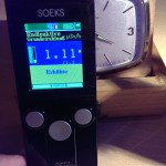
With the SOEKS 01M Geiger counter, an industrially manufactured device, I have now again “scanned” objects in the area.

IMAG1289
SOEKS 01M

Again, I realized that some of the old clocks in my collection are equipped with radium-painted dials. The SOEKS shows here a radiation exposure of about 1.11 microSievert per hour. The environmental load is displayed at approx. 0.14 uSv / h.IMAG1290

But in my mother’s kitchen, I found a beautiful, colorful old vase that displayed about 10uSv / h. (The thing is now in the far corner of the cellar).

It should be uranium paint. (To see orange / red painting in the video below)


Taster day in technology

Loading

In the last two days we received a visit from two young gentlemen from the fourth year of the Villach High School Sankt Martin. Mr. Martin Ungermanns and Mr. Fabian Treu came to us as part of a “taster program” of the middle schools. The two students can participate in the “world of work” and get some insights into the technology.

IMAG1279
deepened in the soldering work

The program included work such as assembling and soldering of electronic kits (the well-known shaker cube), a small series work (flashing of PIC microcontrollers), exposure and etching of circuit boards, milling of aluminum plates.

As conclusion of the two taster days both high school students were allowed to build up a complete “device”.


IMAG1280
Martin Ungermanns and Fabian Treu

It was a “clap switch kit” that detects a loud sound event via an acoustic sensor and then turns on a relay contact. So that this circuit can also be used meaningfully, the circuit has been extended by a self-made power supply, all installed in a plastic housing and equipped with power cable and Schuko coupling. So any consumer (eg a floor lamp, TV) can be switched on and off with this switchgear by simply “clapping” …

Radioreceiver in a retro look – Update: The case

Loading

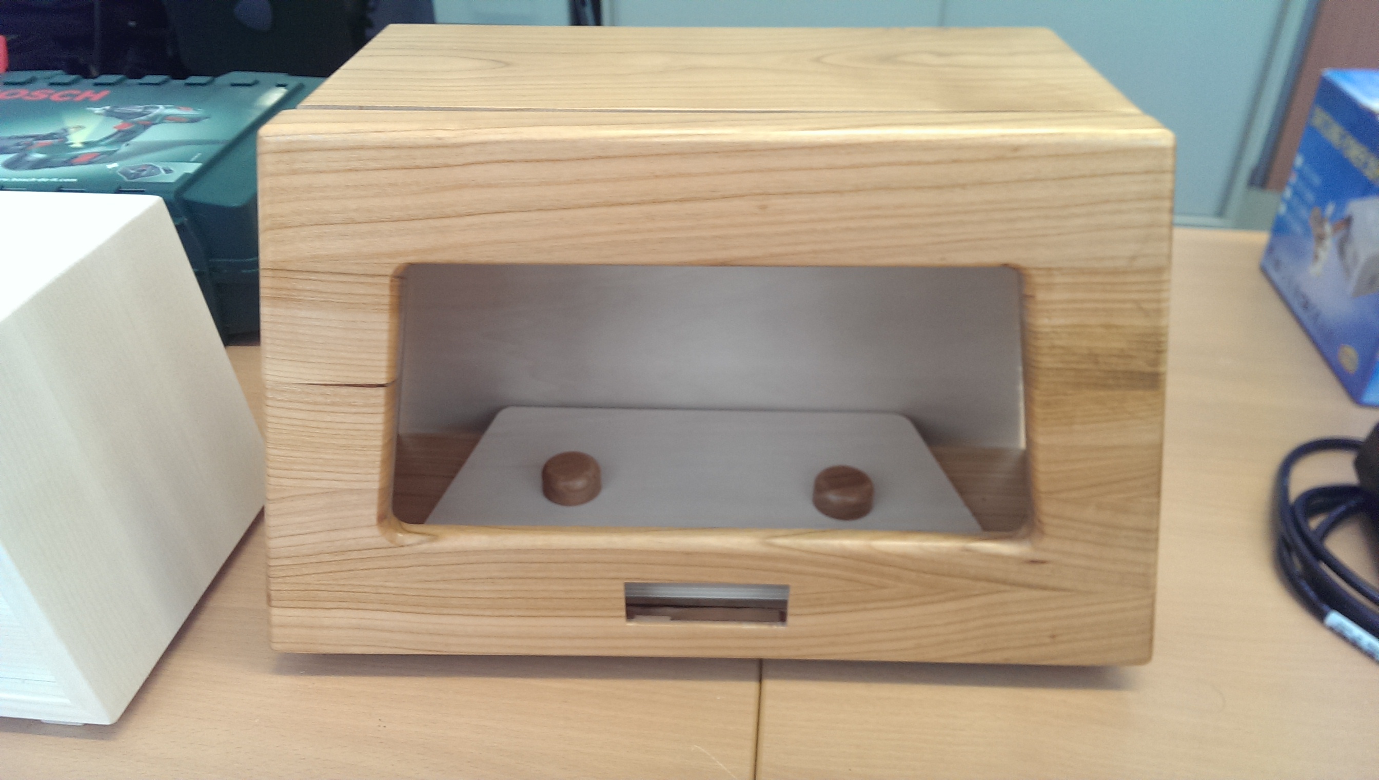
IMG-20150130-WA0000-2 It’s time! The first picture of the absolutely real wooden housing for radio electronics is here. A beautifully crafted housing made of glued elements. This work comes from Gebhard’s hands, a master carpenter from the Upper Carinthian region;)

IMAG1272
Housing with holes for the speakers

Jetzt kann das Nostalgie-Radioprojekt wieder einen Riesenschritt nach vorne machen.

frontpanel
This will be the aluminum front panel

The case is on our table. First, the holes for the speakers were drilled. Later these should be covered by a milled aluminum panel. So the next step is to construct the milling data for the front panel. Here again the layout tool “Eagle” is used. The data can simply be exported as a “.dxf” file and imported into the circuit board plotter software.


UPDATE:

Barely a few minutes, I went to the circuit board plotter, imported the production data, clamped the “two-cutter cutter”, of course, the aluminum blank and off we went.

The speed for the 1mm cutter I have chosen with 60000 rpm and set the feed rate to 1.5mm / s in both axes. Cooled and lubricated was the way with alcohol.

A not negligible amount of work is, by the way, the cleaning of the plant after the work done … 🙂

IMAG1281


Radio in retro-look – KnowHow for the apprentice – Part 2

Loading

… to realize the volume control via the microcontroller, a “digital potentiometer” X9C102 was simply used. It is controlled directly by the controller with a “direction input Up / Down” and a “count input”. Internally, this IC consists of 100 resistors connected in series whose “tap” is determined by counting input. So a simple matter to control the signal level of the preamplifier in 100 steps ….


Continued from Radio Part 1
The controller should now be operated via a push / turn wheel (rotary encoder with push button). In order to be able to evaluate the direction of rotation of rotary encoders, a second pulse output is required. The two pulse outputs must be shifted in their sequence depending on the direction of rotation (phase shift). In order to convert the pulse sequence into a direction signal and a clock signal, we have set up a small decoder logic using a JK flip-flop and a Schmitt trigger / inverter …

Turnwheeldecoder

The outputs of the decoder logic are now passed directly to three microcontroller inputs. Thus, now a suitable program can be created, which provides a simple menu-driven user interface. The parameters are displayed on a two-line LC display. The outputs of the controller, in turn, control the “digital potentiometers” for the volume setting and, of course, the I²C bus, which sends the commands to the FM module. An additional output allows the switching of a relay, with which, for example, the audio input from the amplifier can be switched between the FM module and an external signal source. The LC display is connected to the controller in 4-bit mode and the backlight of the display is also switched by the controller.

 
PCB fresh from production

After all these functionalities had been defined, we were going to transfer this information to the Layout Tool or the schematic.
Finally, a layout was drawn and made. Subsequently, we could start with the assembly of the board and then carry out the first commissioning. After the adjustment of the amplifier quiescent currents, the development of the Arduino code began. Here, the work is extremely facilitated, since there are many finished libraries here, which can be used directly for its purposes. For example, the only challenge with getting an LC display up and running is to connect the few wires to the uC (microcontroller) and pinpoint the pins in the code. Everything else is done by the library. With this simplification, the functions are then implemented quickly and the first test run can begin.

ready assembled PCB

As a result, the software will be even better – perhaps saving multiple stations, and so on. But the next step will be to build the board into an enclosure modeled on the old radio tube radio receivers. It should be made of solid wood. The operating and display elements are to be installed in an aluminum plate placed on the front of the housing … (Another post on this blog will follow.)

The first functional test can be seen in the video below …


Radio in retro-look – KnowHow for the apprentice – Part 1

Loading

THE IDEA FOR THE PROJECT
A project idea that came to my mind as an ideal apprentice project is to plan and build a radio receiver. With this project, our apprentice should apply the acquired skills in a practical way and set up an FM radio receiver according to the components to be used.
This was done gradually. I came up with the concept in the following parts:

THE AMPLIFIER
First, a simple class A audio amplifier should be built. The apprentice should build the amplifier according to the circuit on the breadboard, metrologically examine and understand above all. In the next step, the Class A amplifier became a Class-AB amplifier. Again, the task of the apprentice was to understand the operation and optimize the breadboard function pattern so that a (not metrologically) at least reasonably “good” acoustic result was achieved.

First functional pattern of the “power output stage”

When this succeeded after some time, he got the task to transfer the determined circuit into a layout tool and expand it to a second channel, while also creating a power supply concept. The power supply should not only supply the amplifier output stage, but also for other components (such as microcontrollers, USB interfaces and what ever came to mind) a + 5V and + 3.3V DC supply available.
After many layout designs, he then presented me with a layout in which the components were symmetrical and technically reasonable (Trimmpotis should be accessible …) were arranged. So he was allowed to make the layout as a functional sample. (etch the board, populate it and try to get it all working).

The learning effect was gigantic: D, because in the implementation of theoretical circuits to a simple breadboard construction and then to the “printed” circuit on the print, there is a lot of sources of error. And they also want to be found and corrected. Our trainee was able to practice patience and precise work.
But in the end, the 440Hz sinewave of the frequency synthesizer sounded from both connected speakers …

Now it was time to think about the signal source, the actual receiver.

THE FM RECEIVER

FM-Receivermodul

In a Chinese online shipping I discovered an FM receiver module with a very compact design (a print with about 12x12mm) on which a complete receiver is integrated. The module is called TEA5767 and uses the eponymous Philips FM receiver chip.
The connections to the module consist of power supply, audio L and R outputs, as well as an I²C bus to control or set the reception frequencies and an antenna and Muteeingang. So ideal to realize a signal source for our amplifier. But that raised further questions.
How should one generate the control signals for the I²C bus, how should the tuning of the transmitters be done, how should the device be operated by the user at all? For all these questions, there is a simple answer: Take a microcontroller. And as the apprentice likes experimenting with the Arduino UNO board, I decided to use an Atmega328, the Arduino UNO controller.

THE HEART OF THE RADIO – THE CONTROLLER

The microcontroller should therefore take over the complete management of the radio, thus fulfilling the following functions:

  • set the stations (generate I²C commands and send them to the radio module)
  • save the tuned stations (in the internal EEPROM of the controller)
  • show all information on a LC display
    take over the volume control
  • generate operation by means of a push / turn wheel (incremental encoder with touch function should take over the entire operation of the radio)
 Folie1
blockschematic

So we had to extend the circuit by a few components. The audio output of the FM module had to be pre-amplified. This was done by a small AudioOPAmp. To realize the volume control via the microcontroller, simply a “digital potentiometer” X9C102 was used. It is controlled directly by the controller with a “direction input Up / Down” and a “count input”. Internally, this IC consists of 100 resistors connected in series, whose “tap” is determined by counting input. So a simple matter to control the signal level of the preamplifier in 100 steps.

continue in the next part

Geiger counter and radioactivity

Loading

One project that had long been of interest to me was the detection of radioactive radiation. After the horrible powerplant accidents in Japan, this idea was recalled. I could still vaguely remember owning an unused counter tube somewhere in my old workshop cellar. – After some search it turned up :). Thanks to the Internet and the search engines, a data sheet was also found quickly. The counter tube is a ZP1400. A self-extinguishing Geiger-Müller counter tube with mica window. The tube is according to data sheet with neon and argon filled as quenching gas. The operating voltage is 400 to 600V. The capacity between anode and cathode is about 2pF. With these and other information from the data sheet i now can tinker a circuit to take the tube in operation. I have used this small project to introduce our apprentice to the board layout at the same time and to get acquainted with the creation of small programs on the Arduino Uno microcontroller board. In this post I introduce only the “old-fashioned” circuit, where only the impact of ionizing radiation is made audible to the count wire. (the typical crackling). This circuit then provided the basis for the apprentice to realize the count of the pulses with the microcontroller and to visualize it on a two-line LCD.
Wiring diagram with high voltage supply and pulse amplifier

Using the well-known layout software Eagle, I have drawn a circuit in which the high voltage is again generated by a switched transformer and subsequent Greinacher cascade. The control takes over this time no 555er, but simply a feedback Schmitt trigger. The time base is set via the coupling resistor and the capacitor. Thus, the high voltage is available for the counter tube. In order to be able to count the impulses, two factors are ensured. The impulse must not exceed a certain height. (Otherwise the following electronics may die) and the pulses should be audible (boosted). So the peaks are limited with a zener diode circuit and put into a “nice” shape with Schmitt triggers and then led to an op amp. At the output of the op-amp then hangs first a small speaker …

Arrangement of components on the PCB

After the circuit board was etched and assembled, it was time to test. But with what? I needed some weak source. I held all sorts of items in front of the counter, but it did not change much. There was a cracking sound from the speaker four to eight times a minute. So I started researching the net again. And came across the term “radium color”. This is the self-luminous color with which the dials of old watches were painted, in order to be able to read the time even in the dark. This information gave me an idea. From my grandfather i inherited once an altimeter of a WW1 aircraft (manufacturer LUFFT) whose dial might have been painted with that kind of color. So get out of the showcase and held in front of the counter tube … The result can be seen in the video.


The oscilloscope picturetube

Loading

At the beginning of my blog, I talked about a small project with an oscilloscope tube. Since there are still pictures in the archive, I do not want to withhold it from the blog here:

Cathode ray tube with high voltage generation


A cathode tube (Braun tube) consists of an evacuated glass bulb in which a hot cathode of tungsten wire is heated by an electric heating wire. The electrons emerge from the surface as a charge cloud (annealing emission). Between the positively charged anode and the hot cathode there is an electric field in which the electrons are accelerated. A pinhole allows the approaching electrons to pass only a bundle of determinable diameter, the actual electron beam. The electron beam can then be further accelerated.
The Braun tube – as it is e.g. is present in a cathode ray oscilloscope – has two capacitor plates each to deflect the electron beam. (X and Y baffles). The tube is a Philips B7S 401 oscilloscope tube. For the sake of completeness, I list some technical data here:
  • Indirectly heated cathode, heating voltage Uf = 6,3V
  • Heating current If = 90mA 
  • time for heating kathode tK =1min
  • total accelerationvoltage Ua= 1,2kV
  • Base point tension of the post-acceleration resistance Ug5 = 300V 
  • acceleration voltage Ug4 = 300
  • focusing deltaUg3 = 20V … 50V
  • pre acceleration volatage Ug2 = 1,2kV
  • reverse voltage Ug1 = -30V … -80V
Connections on the tube socket

The aim of the project was therefore to put the small tube back into operation and to lure her a few pictures. So a drive had to be built. Since the supply voltages are quite varied (6.3V to 1200V), this problem had to be solved first. With a NE555, a few components and an old transformer (240 / 12V) a high-voltage power supply was tinkered.
The principle is simple: A DC voltage is switched on and off very quickly with a small circuit. This switched DC voltage in turn connects with a power transistor, the output side of the transformer. (ie where normally the 12V are applied now fed) The ratio of the transformer works in the other direction :). So arise at the exit ever a few hundred volts. (depending on the switching frequency). In order to produce over 1200V, I have connected a cascade (capacitors and diodes). (Functionality)
So now all voltages necessary for the operation of the tube are available to produce an electron beam. With the aid of adjustable voltage dividers, the beam current and the grids for brightness and image focus can be set.

the fist illuminated spot

The voltages for the baffles are also taken from the high voltage supply and controlled by transistors. Thus, a deflection of the electron beam in both axes is possible.

Plexiglas housing

The transistors in turn are controlled by a small pre-stage, which is fed externally with a voltage of -5V to + 5V – the control voltage for the deflection of the light spot. This control voltage input exists for both axes. I added another input to switch the electron beam to “bare”, ie dark. For this purpose, a corresponding voltage is applied to the corresponding grid, which previously block the electron current to the anode.

connections

Thus, the tube can now be controlled directly from the outside, for example, by means of analog outputs of microcontrollers (Arduino, PIC, etc.) or NI DAQ cards with the extra-low voltages available there. After the first positive test runs with the breadboard electronics I then constructed a clean board and mounted the whole construction on a wooden board and covered with a transparent Plexiglas housing.
All connections are routed via banana sockets to the outside. For example, you can easily draw Lissajous figures on the screen …

Lissajous-figure done withe NI-DAQ

F101 Voodoo Radarmonitor

Loading

From a McDonnel F101 Voodoo came the following sample that I got from a customer back then, with a request to try to bring it back to life somehow.
The thing I’m writing about was a black cylinder about 30 centimeters long and about 20 centimeters across. On one end face of the cylinder was a picture surface as seen from an oscilloscope, with a rotatable scale ring with a 0 to 360 degrees angle label.
The customer told me it was the cockpit radar of a Starfighter jet. Then I began to research what turned out to be relatively expensive at that time, in the mid-90s, especially since the Internet did not yet exist in the form and diversity as it exists today.

picsource: Wikipedia

But at least I found out that the part was really the board monitor of the radar system of an airplane. Namely to the radar monitor of a McDonnel F101.
A twin-engine fighter aircraft of the 50s cold war US Air Force.
In any case, the part came from this plane – wherever the customer had it from. And he asked me if I had any chance of getting it up and running. He meant that he wanted to see the famous, rotating light stroke on the screen.
At that time, I could not find any information or documentation on the part, how to connect the tangle of cables over cables, which came out of the device …

 
frontview of the monitor

So I started dismantling. Several miniature electron tubes, transformers and many smaller tubes with bobbins with immersion cores and many, many capacitors were installed. In the longitudinal axis of the device, the picture tube was housed, with the magnetic deflection was rotatably mounted about the axis of the tube. Say, the complete deflection unit was turned around the tube by means of an electric motor drive.

topview

Since I had no chance to somehow understand the circuit, especially since apparently some components, such as the entire voltage and signal conditioning were not integrated in the monitor, but apparently were installed elsewhere in the plane, so I set out to dismantle everything. All that was left was the picture tube with the mechanics and the deflection coils and the drive. On a breadboard I started to make my own drive for the coil drive. For the deflection coil itself, I built a sawtooth generator with a sufficiently strong power output stage. And for the high voltage of the tube had to serve an old line transformer of a television, which was driven by a NE555 (the old known timer module) and a matching power transistor (some BU508 …).

and it´s turning again

The whole circuit was operated at about 24V and took over 2A. (including cathode heater and electric motor and the scale bulbs that illuminated the labels).
But it worked. On the screen was a green line, which turned at the adjustable rotational speed. That was already everything. There was no beam modulation or the like to draw any simulated radar images. Today you could work together with small microcontrollers like Arduino and co, quite simply …

The Stirling engine

Loading


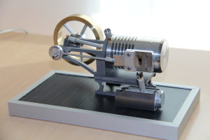
the finished machine

As a gift I received in the winter of 2014 a kit for a model of a Stirling hot air machine. The design plans, as well as the largely prefabricated parts, come from Mr. Klaus Künneth, the operator of the website www.kk-stirlingmotor.de

To build and install only a little manual skill and a few gauges and tools are needed. (Stand drill, drill and tap, a grinding block with polishing wheels, at least a sliding calliper, a little clear coat and machine oil). On some parts holes of various diameters are to be made. For example, on the flywheel, the connecting rods. In the cylinder and head cover, the mounting holes are to drill and thread to cut.

drill the flywheel

After preparing all the items, everything is polished to a high gloss on the polishing machine. Then you can start with the assembly. All in all, one should take a few hours to have the model beautiful, meticulous and functional. From a few parts is then also quickly made a small spirit burner, which provides the necessary heat for operation under the working piston. Everything together is then mounted on the clear lacquer-sealed wooden base plate.

finished polished unit
The functioning of the Stirling engine is described by Mr. Künneth on his website as follows:
 
“The Stirling engine is also called a hot air engine and is a heat engine in which a closed working gas such as air (in this case) or helium is alternately heated and cooled from outside at two different areas (hot side and cold side) to generate mechanical energy. The Stirling engine works on the principle of a closed cycle and is an example of the energy conversion of a poorly usable form of energy (thermal energy) in the better usable form of energy of mechanical energy. The Stirling engine can be operated with any external source of heat (or cold) (solar, wood, gas, liquid fuels, in this model with spirit).”
 
short video link: