
Keysight oscilloscope dies in standby – power supply repair
![]()
An interesting problem has arisen with the measurement technology in the laboratories at my workplace. I use the term “measurement technology” to describe the equipment of a laboratory workstation for basic training. There are a total of nineteen laboratory workstations, each equipped with two laboratory power supplies, two desktop multimeters, a Keysight signal generator and a Keysight (Agilent) oscilloscope of the Infiniivision DSO-X 20xx series. All devices are network-compatible and are connected to the corresponding workstation computer via LAN. This means that the measuring devices can be accessed using different software (Agilent VEE, Matlab, LabVIEW etc.). The devices were purchased around three years ago and replace the almost twenty-year-old laboratory equipment.
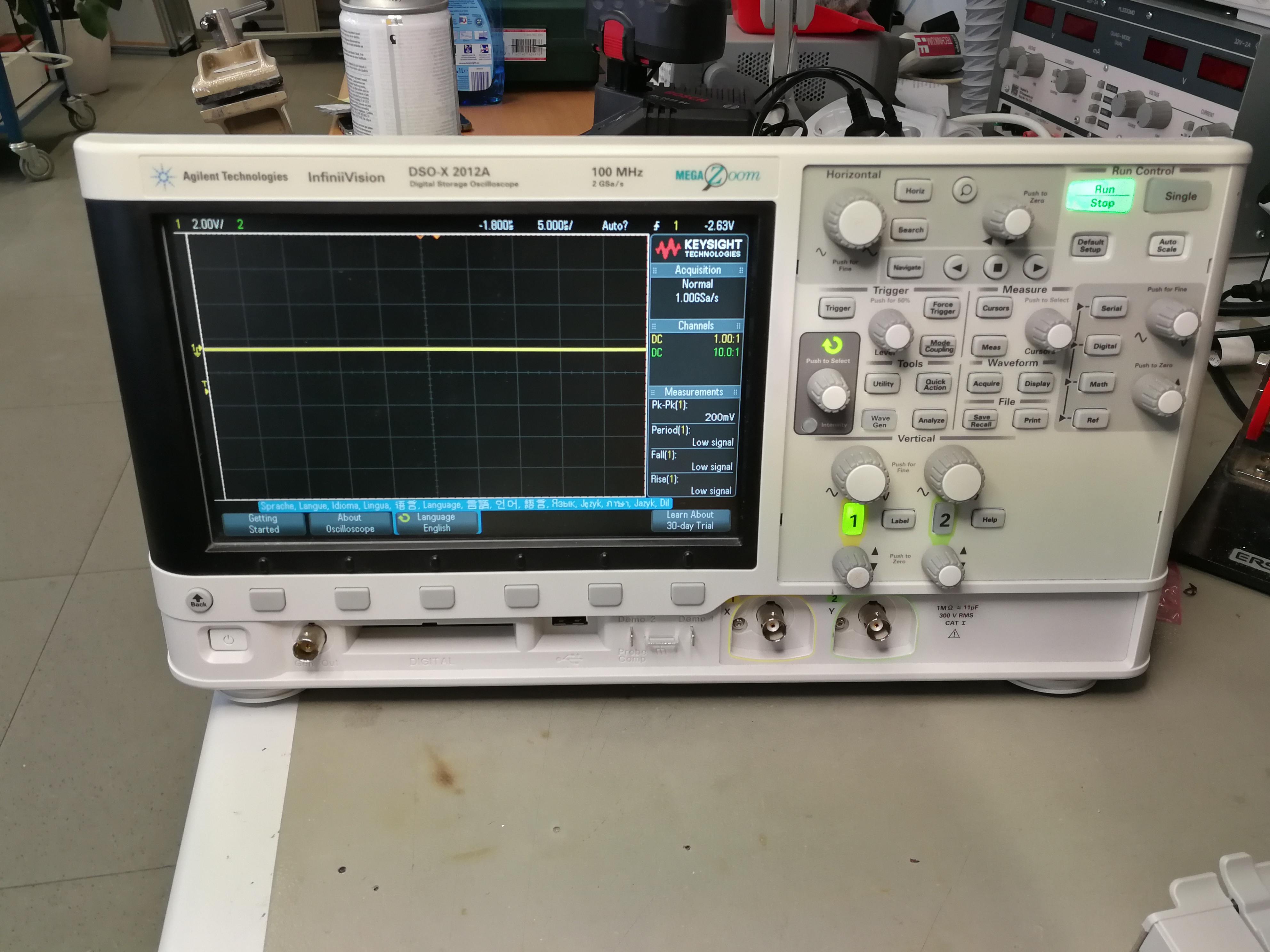
However, it has now happened that the DSO-X2012A oscilloscope at one workstation no longer showed any signs of life. It occasionally happens that during laboratory exercises or when working freely in the laboratories, a student presses the emergency stop switch of the workstation and thus de-energizes it. But this was not the case. All the devices connected to the workstation worked, with the exception of the DSO. Voltage could also be measured at the end of the IEC plug. So the problem could only be with the oscilloscope itself. The rear panel is quickly unscrewed, a shield plate removed and the power supply unit is exposed. The first visual inspection immediately revealed the large filter capacitor with its upwardly curved cap. But first things first.
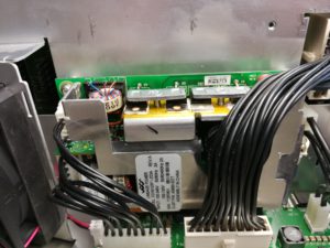
Power supply unit of the Infiniivision
The mains voltage was measured at the AC pins of the mains input, but no DC voltage was measured at any of the outputs of the power supply unit. Regardless of whether the power switch of the device was switched on or off. This suggests that the power supply unit is defective.
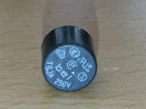
Input fusing
First, the power supply unit was removed and examined, starting with the AC input side. The print fuse in the area of the mains filter was the first defective component to be noticed. It is a slow-blow 6.3A/250V fuse. As a blown fuse always has a reason to switch off, the search continued. The mains rectifiers were OK, but the 100uF / 420V electrolytic capacitor, which is used to smooth the DC voltage on the primary side, had already suffered some thermal damage and was bloated.
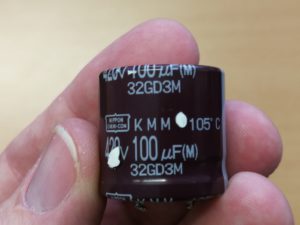
original electrolytic capacitor 100uF /420V /105°C
Its capacity was also no longer within the nominal range. But even that was not the direct reason for the fuse blowing. This was quickly found. A mosfet used to control the transformer was low-resistance. More precisely, it had a short circuit between all the connections.
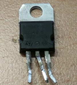
Mosfet STP12NM50
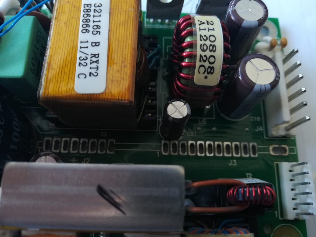
The following picture shows the installation positions of the components. These have been replaced. The mosfet was replaced with an original type and the power supply capacitor was replaced with a 100uF / 450V / 105°C type. Although it is about five millimeters higher, it fits easily into the power supply unit.
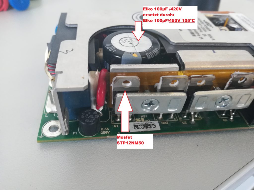
Installation position of the capacitor and the mosfet
Two SMD resistors on the back of the power supply board were defective in the area of the gate connection of the mosfet. These were an SMD resistor of size 0805 with 5.11 Ohm and an SMD resistor of size 1206 with 2.0 kOhm. The picture below also shows the installation position.
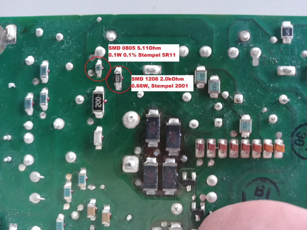
Mounting position of defective SMD resistors
After all the components mentioned had been replaced, a first functional test was carried out. However, this was sobering, as the power supply unit was still not working. The fuse remained intact and the DC voltage on the primary side was stable. But the gate of the mosfet was not activated – unfortunately. Because now came the time-consuming part of the repair. On the power supply board, installed upright, there is another board on which several controller ICs are installed. If you follow the gate line from the Mosfet, it ends at a pin on this control board. So this must be removed.
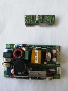
Controller board removed
To do this, the cooling plate had to be removed first. Then it became a bit tedious, because the controller board is not connected to the main board via a pin header or plug connection, but the contact pins are laid out and milled out. This means that the desoldering work has to be carried out very carefully so as not to damage the conductor tracks at the ends of the milled pins.
Mainboard without controller board
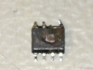
UC3842B
Once the removal was successfully completed, the controller board could be inspected. Lo and behold, the line routed from the gate of the mosfet ends at pin 6 of a small IC. This is a UC3842B VD1R2G. The housing of this IC was blown up. In addition to the controller IC, a SOT23 PNP transistor (PMBT 2907A) was also dead and had a low resistance on all pins.
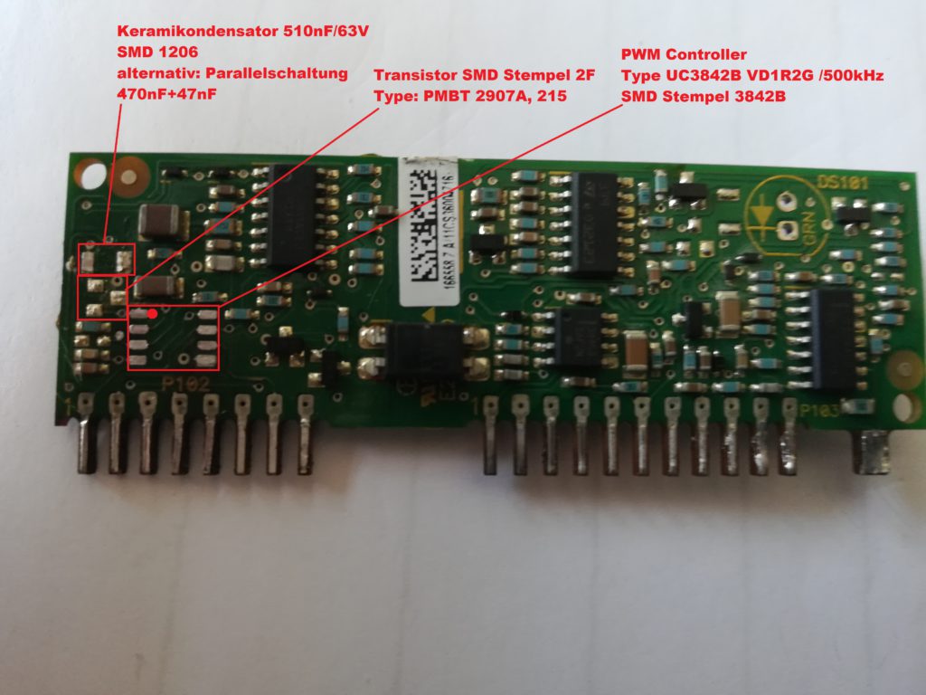
Installation position of the defective components
After replacing the defective components, the power supply unit was reassembled and a function test was carried out. The oscilloscope started up again and the power supply unit did its job.
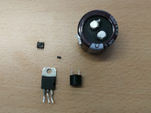
defekte Bauteile

Result after successful repair
It would now be interesting to find out why the power supply gave up the ghost after just three years. Especially as the oscilloscopes do not run continuously, but are only switched on during the relevant courses. We noticed the following: The oscilloscope is permanently connected to the power supply. However, the oscilloscope’s power switch does not switch off the AC supply, but only the controller control in the secondary area of the power supply unit. This means that the power supply unit operates in standby mode when it is switched off. And we have noticed that all oscilloscopes that are switched off have a power loss in standby that heats up the mosfets and especially the 100uF electrolytic capacitor. This would explain the bloated, dried-out electrolytic capacitor and the subsequent death of the power supply units. To verify this, the temperature of the components was measured on several devices that had not been switched on for days.
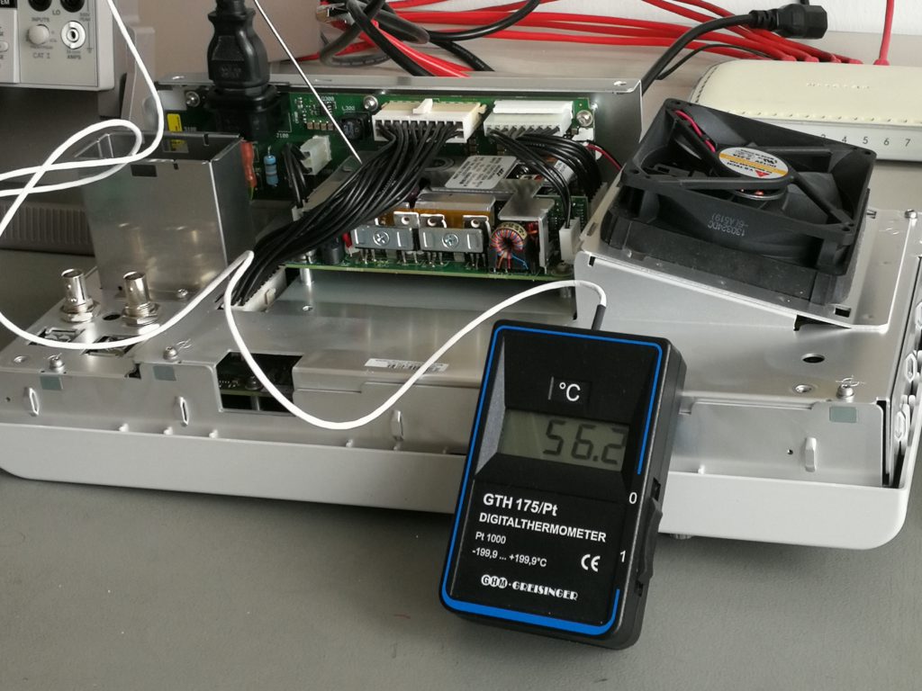
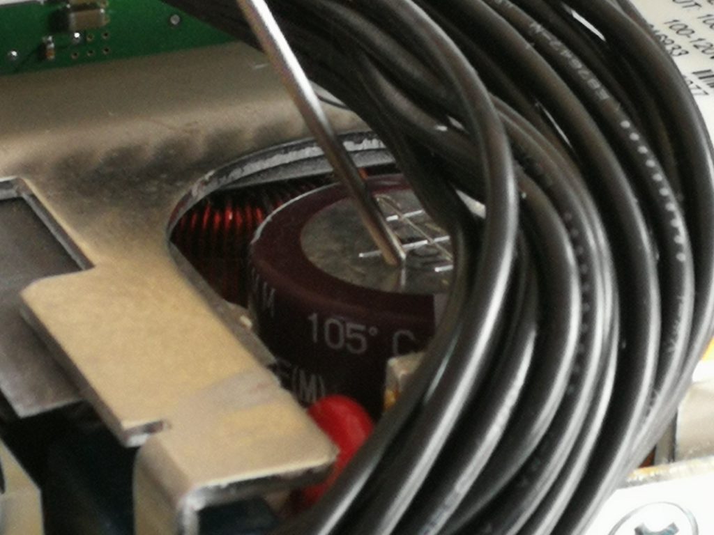
Thermal sensor on the electrolytic capacitor surface
The following could be determined here. Both the surface of the capacitor and the cooling plate of the mosfets measured temperatures of 56°C to almost 60°C when switched off. Should this be the case?
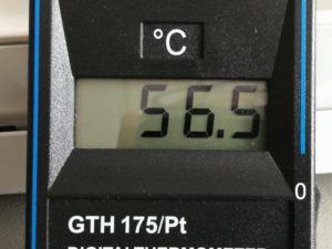
Temperature measurement on the electrolytic capacitor
Here are the required components:
- resistor 5R11 0,1W 0,1% Farnell Nr.: 1872688
- resistor 2k0 0.66W Farnell Nr.: 721-9844
- PNP Transistor SOT23, SMD Stempel 2F Type PMBT2907A, 215 Farnell Nr.: 1626500
- PWM Controller IC, UC3842B VD1R2G / 500kHz Farnell Nr.:2845218
- capacitor 100uF / 105°C / 450V
- fuse T6.3A 250V
Jun2019: Order numbers updated


2 Responses
I am grateful for your post. The power supply in my MSOX2024 failed and I had little hope of replacing it for an affordable cost. You saved the day with the Meanwell supply that was in stock at Digikey for <$75 including Trump's tariff.
thanks a lot for the feedback