
Selfmade ROM module for Vectrex
![]()
edit Nov. 2024: I keep receiving requests to make the Gerber files for the circuit boards available for reproduction. The download is now possible with this link:
 For the Vectrex game console a home arcade machine from 1982, there were, or there are a very limited number of game titles available. I will present the Vectrex itself, or the restoration of this darling, in a separate article.
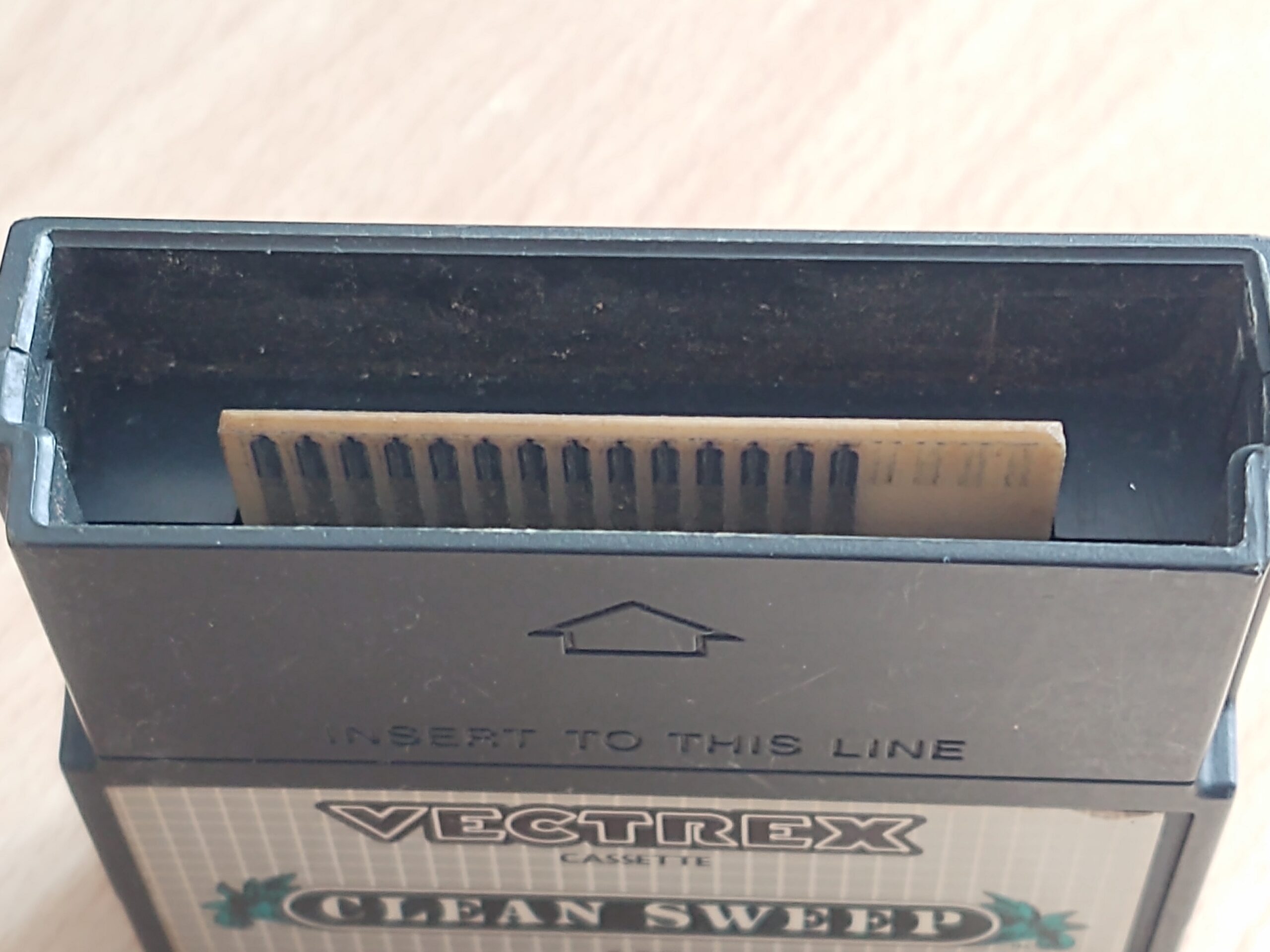
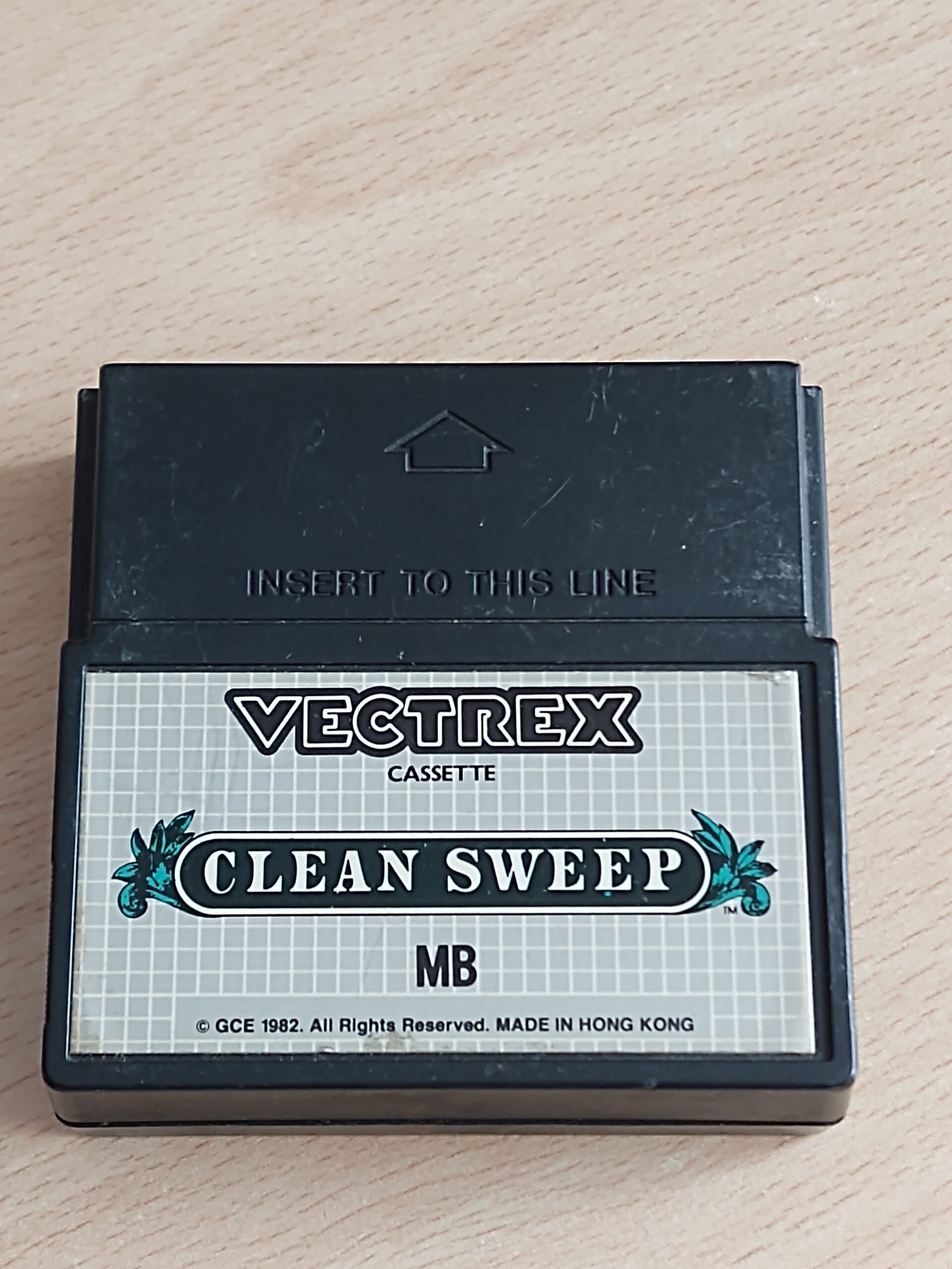
The games were available in the form of ROM modules and had to be inserted into the side of the console. Today, like the console itself, they are pretty rare and difficult to find. In terms of price, they are usually not bargains either. There are also replicas, multiroms and some DIY projects that keep the game program or even several games saved on the basis of the old EPROMS and were thus playable via a “module”. Since I also have all sorts of Eproms with different sizes in the component store and also got a couple of 27C512 Eproms sponsored by a colleague (thank you Jürgen), I just had to try to tinker with a ROM module.
originale Vectrex ROM-Module board
So quickly thought about what I would need for this. Here is a small list:
- old EPROMS (I use Eproms that can be erased with UV light)
- an Eprom programmer (in the back corner of a box I found a ChipLab programmer with a parallel interface)
- an old computer with a parallel interface and an older operating system (Windows XP). Fortunately, I once again did without disposal and brought an old laptop back to life.
- software for the programmer (here I use “ChipLab” which can run on WindowsXP with the help of “porttalk22”)
- the binary data or HEX files of the original ROM modules (you can use the internet search for this)
- a layout tool (Autodesk Eagle)
- a craft shop where you can etch circuit boards, or an account with
- a Far Eastern PCB manufacturer
- Soldering tools and small parts
- and of course a Vectrex – otherwise none of this makes any sense
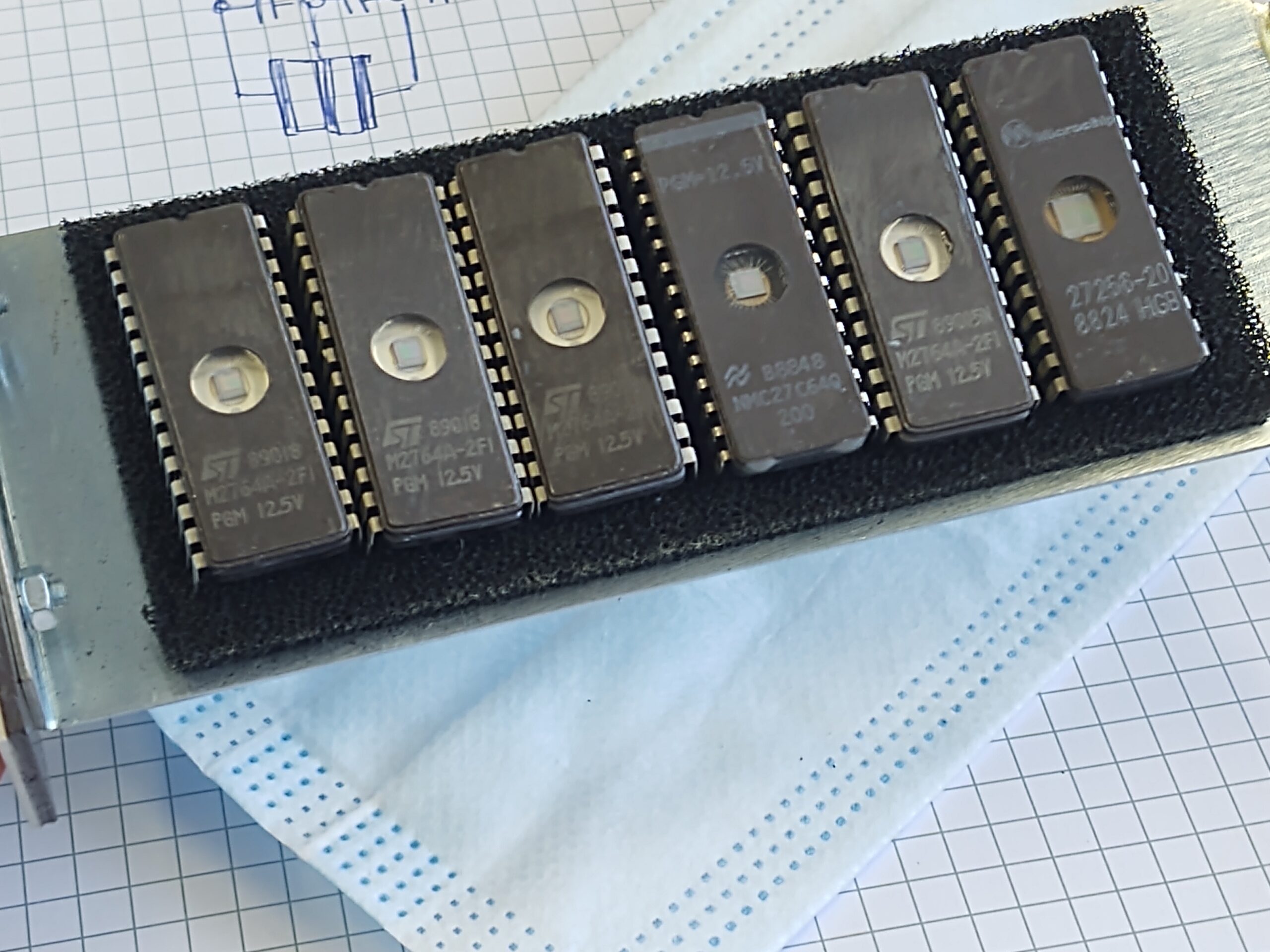
EPROMs
In order to determine the memory requirements of the Eproms, I first have to know the size of the games. Here is the list of titles and their size:
Games with a size of 4 kB (4 kilo bytes). This corresponds to an address range from hex 0000 to 0FFF
- Armor Attack
- Art Master
- Bedlam
- Berzerk
- Clean-Sweep
- Cosmic Chasm
- Engine Analyzer
- Hyperchase
- Minestorm 2
- Rip Off
- Scramble
- Solar Quest
- Space Wars
- Star Castle
- Star Hawk
- Star Trek
Games with a size of 8 kB (8 kilo bytes). This corresponds to an address range from hex 0000 to 1FFF
- Animaction
- Blitz
- Fortess of Narzod
- Heads Up
- Melody Master
- Pitchers Duel
- Pole Position
- Spike
- Spinball
- Tour de France
- Web Wars
Games with a size of 12 kB (12 kilo bytes). This corresponds to an address range from hex 0000 to 2FFF
- Dark Tower
Next, I’ll take a look at the Eproms for pinout and size. I have two sizes available for the number of pins. Eproms with 28pin and 32pin in DIL housing. The following types belong to those in the 28-pin housing:
- 27c64 8k x 8 bit so 64 kb (kilo Bit)
- 27c128 16k x 8 bit so 128 kb (kilo Bit)
- 27c256 32k x 8 bit so 256 kb (kilo Bit)
- 27c512 64k x 8 bit so 512 kb (kilo Bit)
picture from (www.futurlec.com)
picture from (www.futurlec.com)
The pinout is identical except for the different number of address lines. However, the 1Mbit variant 27C1001 (27C010) has a different pinout.
Bild von (www.futurlec.com)
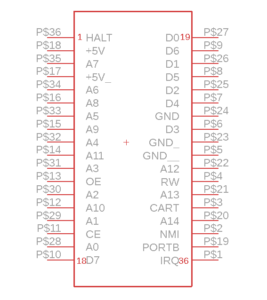
The next step is to look at the pinout of the Vectrex module bay. The pin numbers of the module are marked in the picture below.
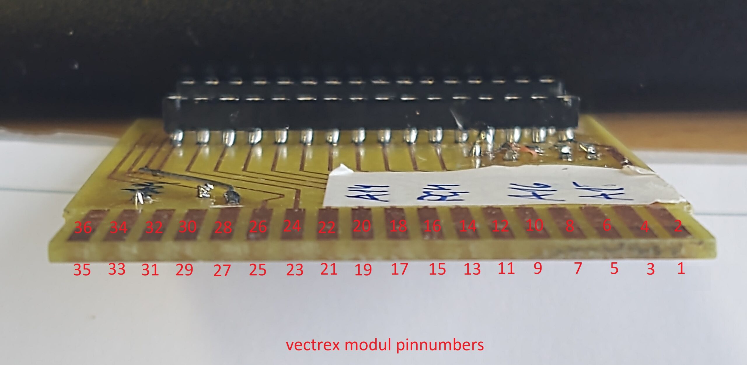
Pin Nummerierung des Vectrex Moduls
The signals associated with the pin numbers can be found in the Vectrex circuit diagram of the mainboard. The picture below shows an extract from the circuit diagram with the area of the 36-pin cartridge connector. (Source: console5.com)
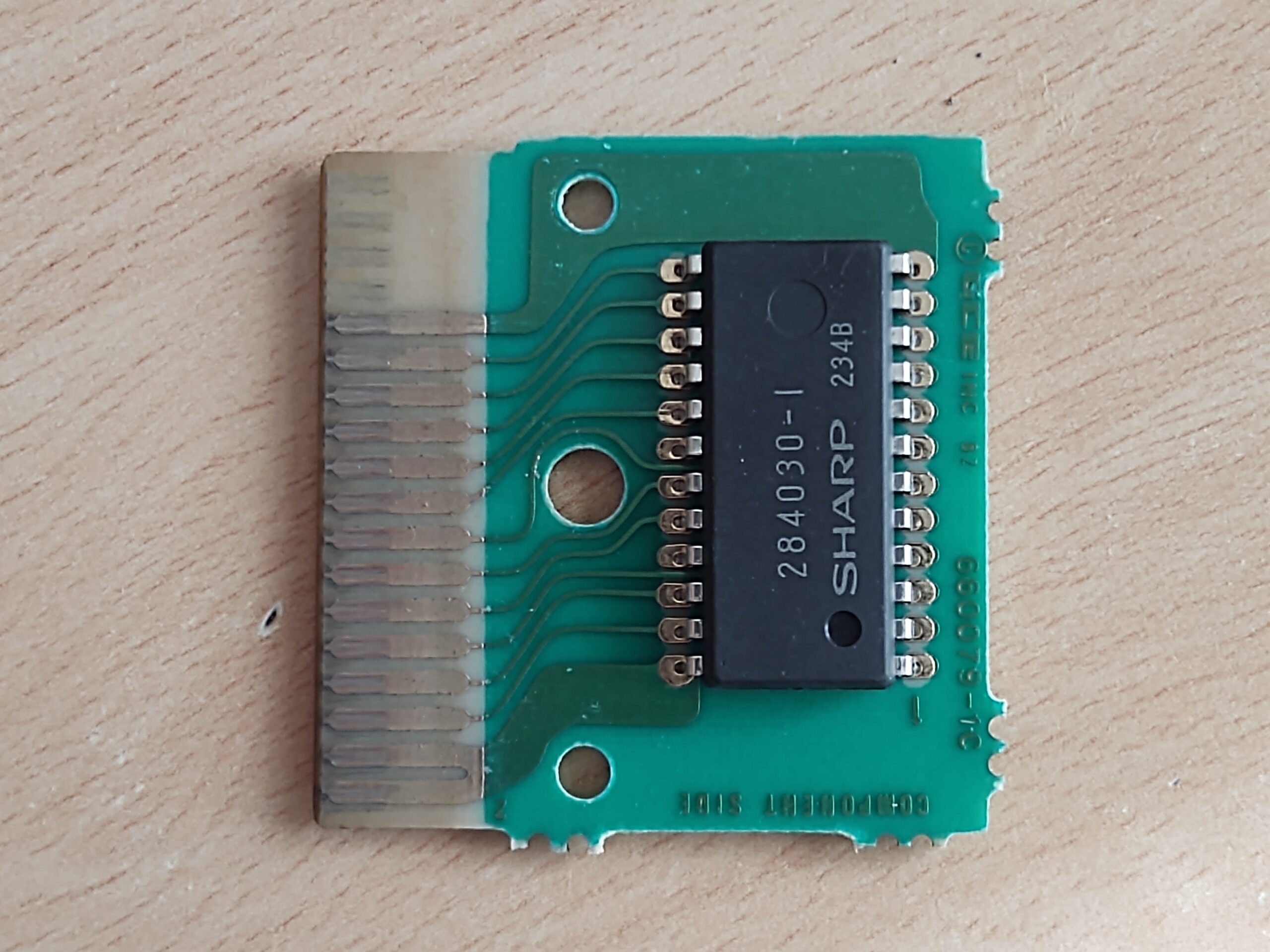
 All the information you need to start with a circuit diagram and layout has now been collected. I looked for an eagle layout for the circuit board connector on the web. But nothing could be found straight away. So an original ROM module had to be used as a reference for the dimensions and spacing of the contact pads. With the dimensions removed in this way, it was quickly done and I had drawn a new Eagle component and saved it in the library.
vectrex_connector.lbr
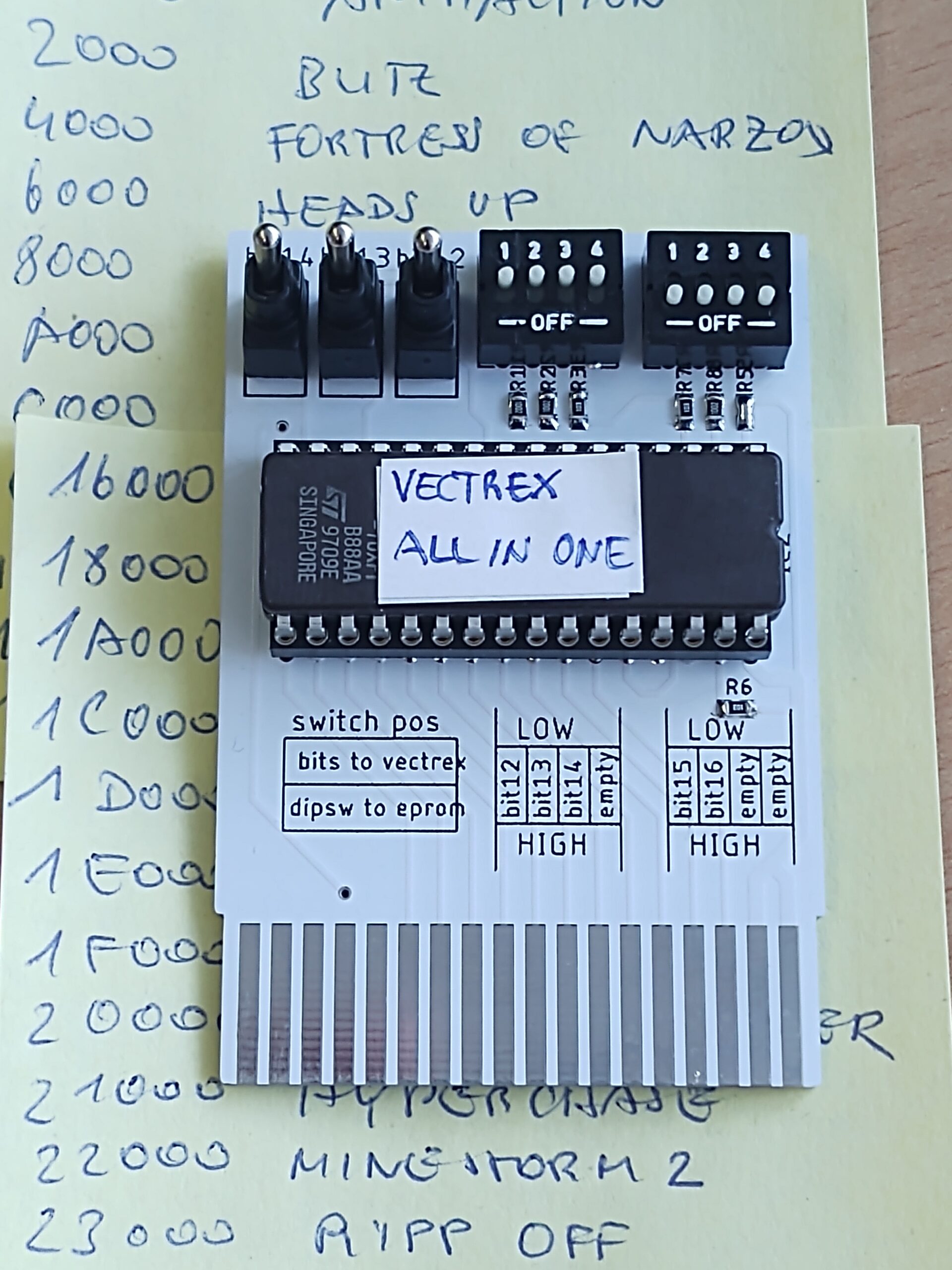
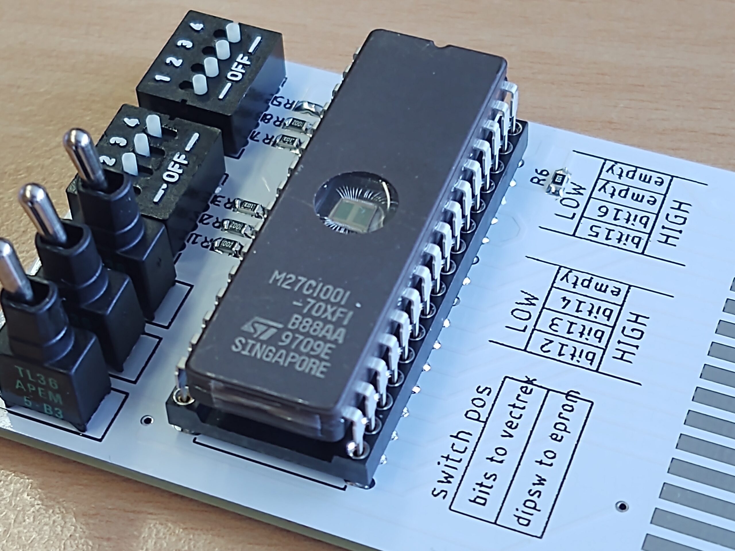
I drew two variants of the module circuits. One for the EPROMs with 28 pins and one for the 1Mbit ROMs with 32 connection pins. (Since there is also space for more games here) In order to be able to distribute all possible sizes of games differently on the EPROM, I have made address bits 12, 13 and 14 switchable. In such a way that these three address lines can either be controlled by the Vectrex or selected externally by the operator using DIP switches (L / H). Bits 15 and 16 (can also be selected via DIP switches).

The following table shows a few examples of how the start addresses of the games can be selected.
| bit 16 |
bit 15 |
bit 14 |
bit 13 |
bit 12 |
bit11-bit0 game adresses |
adresses start – end (hex) |
| L | L | L | L | L | at 8k game | 0000 – 1FFF |
| L | L | L | H | L | at 8k game | 2000 – 3FFF |
| L | L | H | L | L | at 8k game | 4000 – 5FFF |
| L | L | H | H | L | at 8k game | 6000 – 7FFF |
| L | H | L | L | L | at 8k game | 8000 – 9FFF |
| L | H | L | H | L | at 8k game | A000 – BFFF |
| L | H | H | L | L | at 8k game | C000 – DFFF |
| L | H | H | H | L | at 8k game | E000 – FFFF |
| H | L | L | L | L | at 4k game | 10000-10FFF |
| … | … | … | … | … | and so on… | … |
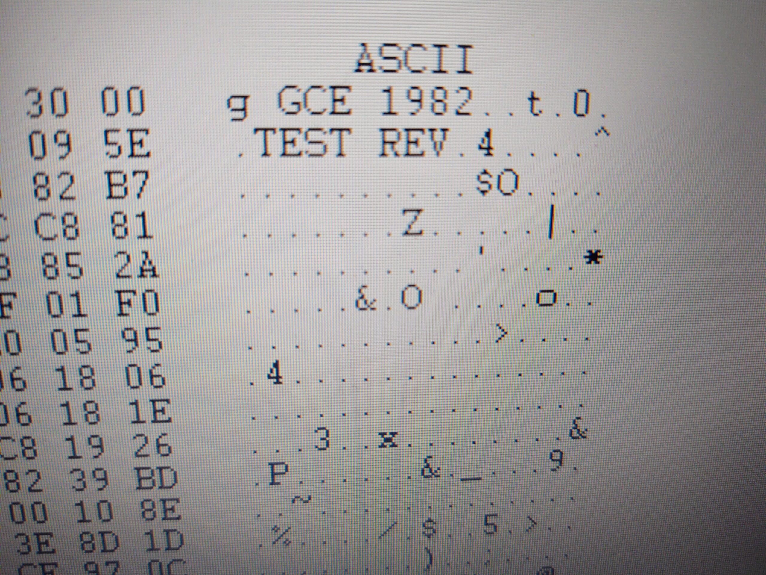
Ansicht im Hex Editor
Provided, of course, that the game data was written to the EPROM in this way. To do this, I use one of the many freeware hex editors (HxD) and assemble a binary file from the individual game images. This “file” is then imported into the ChipLab software, the correct EPROM is selected from the database, then the chip is inserted into the programmer and off you go … (First, check again whether the chip is empty. Otherwise it has to ” topless “in the sun, or under the UV lamp (for about 15-20min)
Eprom inserted to the programmer
Once the chip has been filled with bits and a layout has been made from the circuit diagram, a prototype can be etched. To do this, I was able to use our company’s etching system in a short lunch break and remove the unnecessary copper from the board using etching technology.
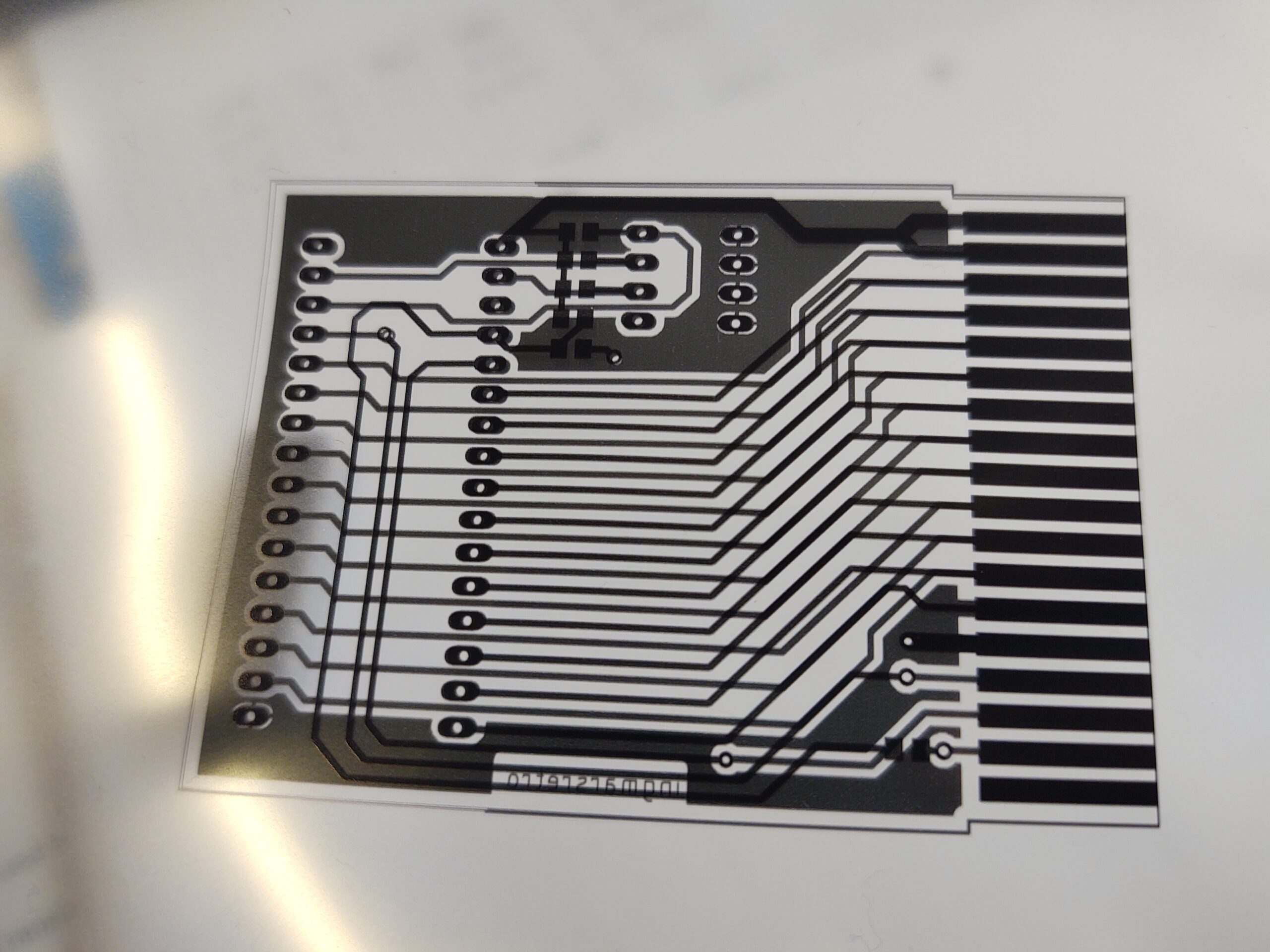
pcb layout printed on foil
After exposing a double-sided board coated with photopositive lacquer and then developing it, the excess copper can be removed with EisenDreiChlorid. What remains is the desired structure.
 Sometimes a selfie in between. It takes about 57 seconds to expose the circuit board to UV light. Enough time to take stupid photos with the phone: D
The next step is to drill the holes in the board. The vias (VIAs) from the top to the bottom layer are not implemented in the prototype by galvanic application of copper in the holes, but by hand by pushing a piece of silver wire through the hole and then soldering it on both sides.
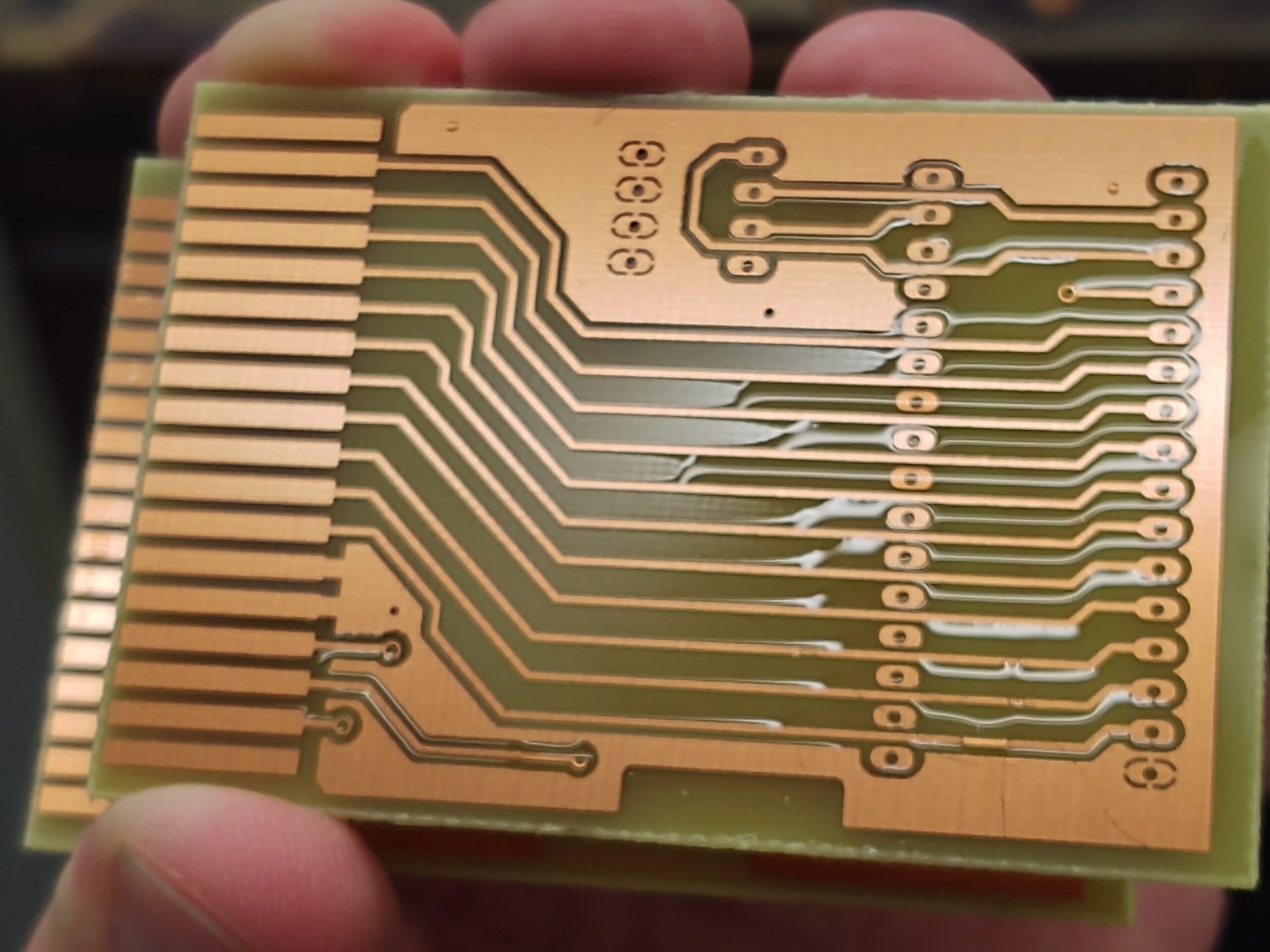
the etching is completed
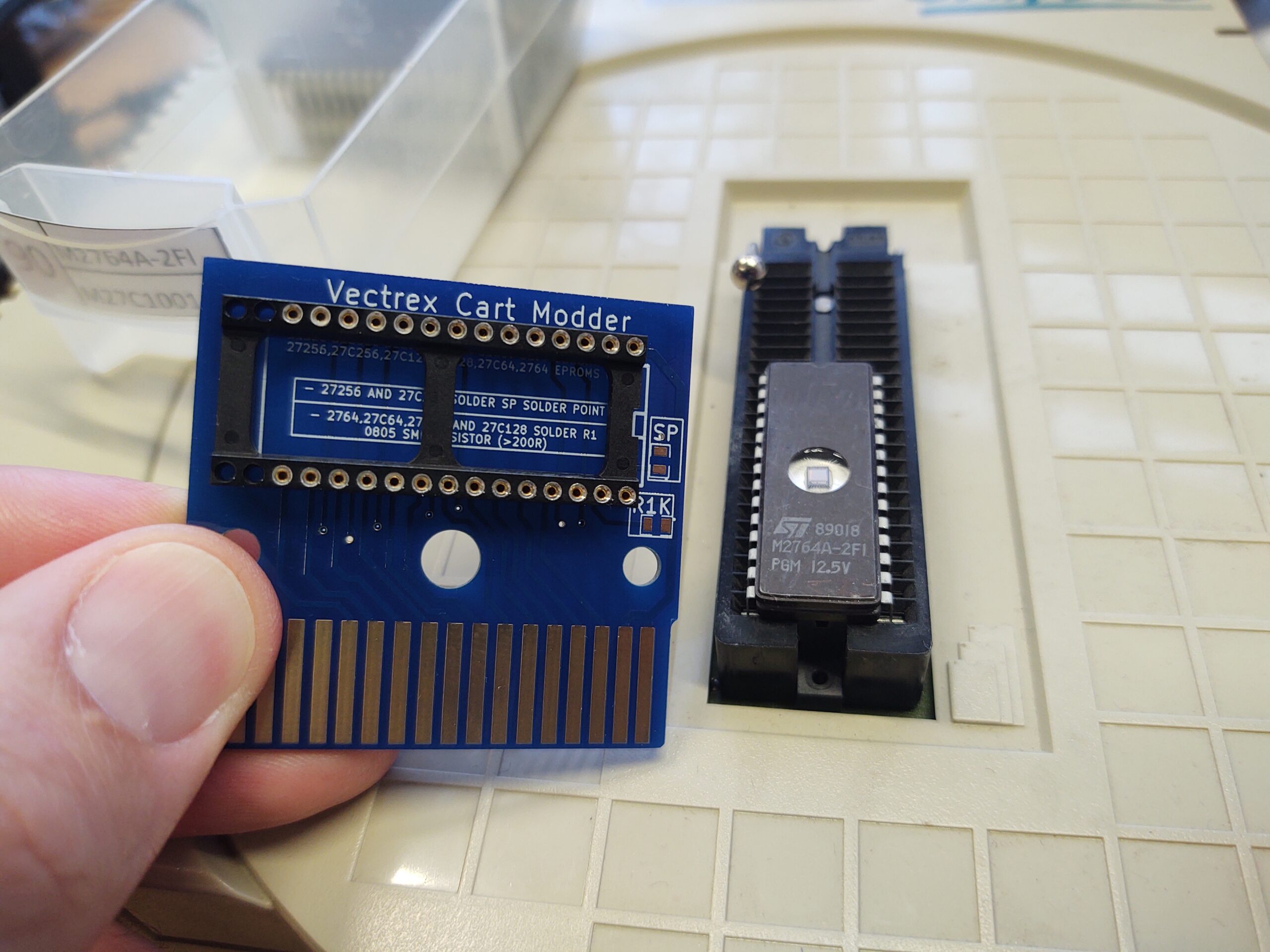
Now all that’s missing is the assembly. But it is done very quickly. Because apart from the IC socket, a couple of pull-up resistors and the DIP switches, there isn’t much on the board. So solder the few parts, put the chip in the socket – and the ROM module is ready.
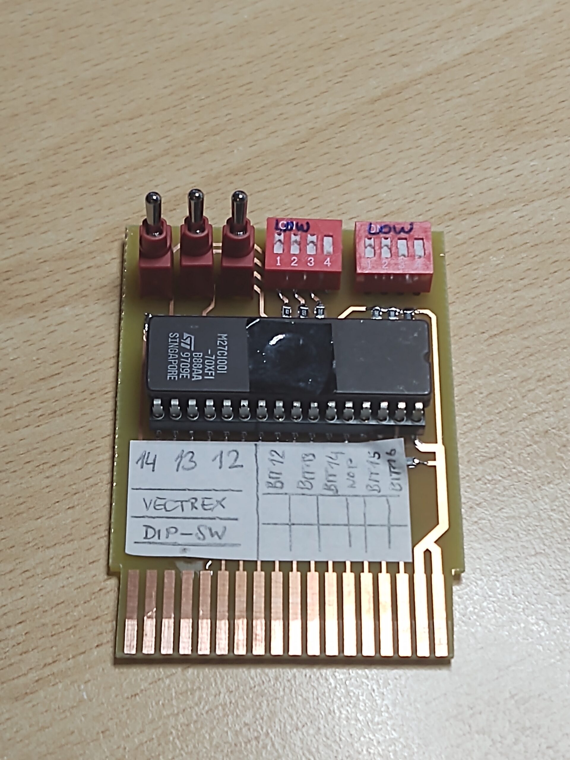
ready assembled ROM module
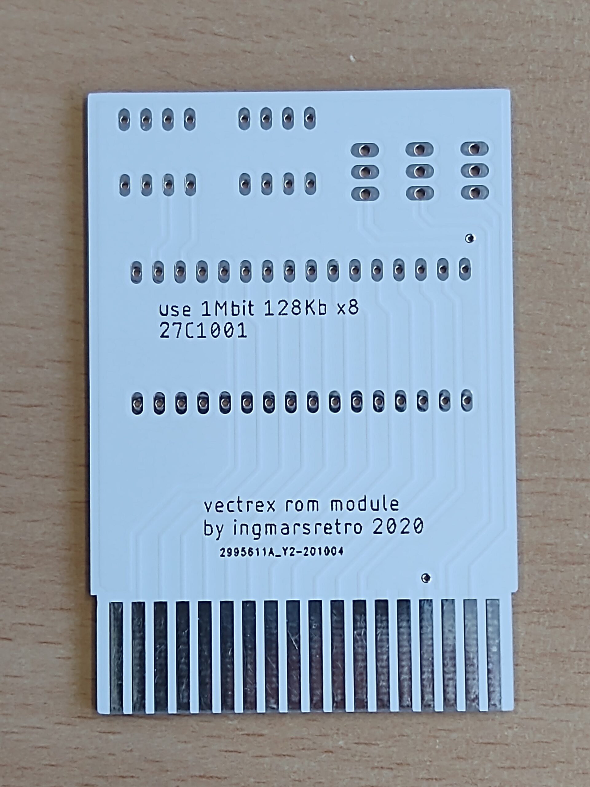
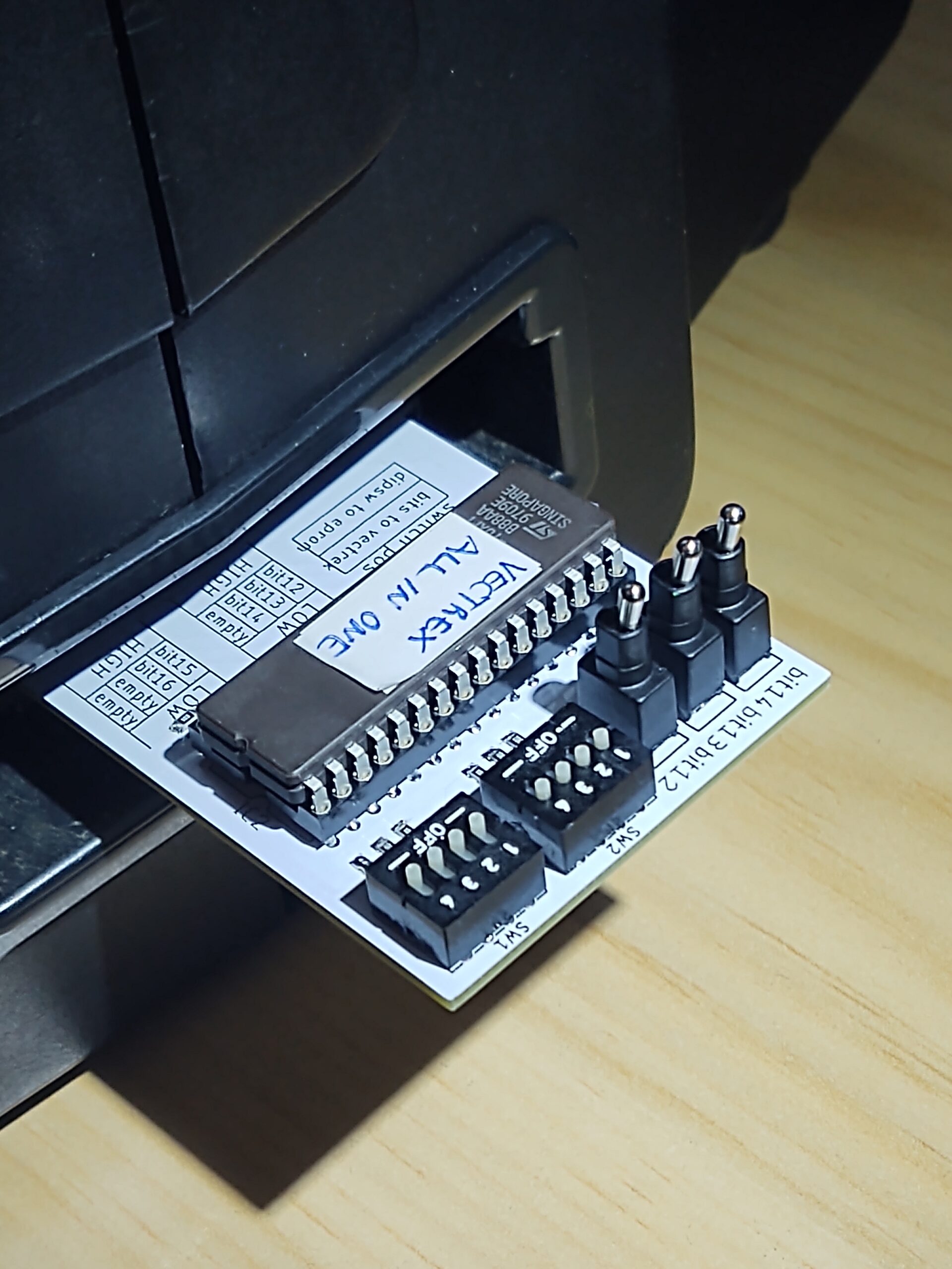
What the finished module looks like on the Vectrex and, above all, how it works, I’ll show you in a short video. I also embellished the board a bit and commissioned it as an industrially manufactured circuit board from a Far Eastern printed circuit board manufacturer …
(small update on October 20, 2020)
The circuit boards made in far east have come and, in my opinion, look quite acceptable. A board is quickly assembled … here is the result:


4 Responses
Hello,
Would you like to share the gerbers for the 27C256 “vectrex cart modder” pcb ?
Thank you !
hello,
the next days i will edit the blog an add a download link.
br
Hi,
same request here.
I would like to try making one or few cartridges, but without gerbers, will not manage. Have no PCB design skills myself.
What I have however are eproms, eprom programmer and soldering station 🙂
Cheers!
you find a link with the gerber files at the top of the blogpost