Tag Archives: MB

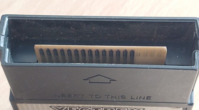
Selfmade ROM module for Vectrex

Loading

For the Vectrex game console a home arcade machine from 1982, there were, or there are a very limited number of game titles available. I will present the Vectrex itself, or the restoration of this darling, in a separate article.

The games were available in the form of ROM modules and had to be inserted into the side of the console. Today, like the console itself, they are pretty rare and difficult to find. In terms of price, they are usually not bargains either. There are also replicas, multiroms and some DIY projects that keep the game program or even several games saved on the basis of the old EPROMS and were thus playable via a “module”. Since I also have all sorts of Eproms with different sizes in the component store and also got a couple of 27C512 Eproms sponsored by a colleague (thank you Jürgen), I just had to try to tinker with a ROM module.

originale Vectrex ROM-Module board

So quickly thought about what I would need for this. Here is a small list:

  • old EPROMS (I use Eproms that can be erased with UV light)
  • an Eprom programmer (in the back corner of a box I found a ChipLab programmer with a parallel interface)
  • an old computer with a parallel interface and an older operating system (Windows XP). Fortunately, I once again did without disposal and brought an old laptop back to life.
  • software for the programmer (here I use “ChipLab” which can run on WindowsXP with the help of “porttalk22”)
  • the binary data or HEX files of the original ROM modules (you can use the internet search for this)
  • a layout tool (Autodesk Eagle)
  • a craft shop where you can etch circuit boards, or an account with
  • a Far Eastern PCB manufacturer
  • Soldering tools and small parts
  • and of course a Vectrex – otherwise none of this makes any sense
EPROMs

In order to determine the memory requirements of the Eproms, I first have to know the size of the games. Here is the list of titles and their size:

Games with a size of 4 kB (4 kilo bytes). This corresponds to an address range from hex 0000 to 0FFF

  • Armor Attack
  • Art Master
  • Bedlam
  • Berzerk
  • Clean-Sweep
  • Cosmic Chasm
  • Engine Analyzer
  • Hyperchase
  • Minestorm 2
  • Rip Off
  • Scramble
  • Solar Quest
  • Space Wars
  • Star Castle
  • Star Hawk
  • Star Trek

Games with a size of 8 kB (8 kilo bytes). This corresponds to an address range from hex 0000 to 1FFF

  • Animaction
  • Blitz
  • Fortess of Narzod
  • Heads Up
  • Melody Master
  • Pitchers Duel
  • Pole Position
  • Spike
  • Spinball
  • Tour de France
  • Web Wars

Games with a size of 12 kB (12 kilo bytes). This corresponds to an address range from hex 0000 to 2FFF

  • Dark Tower

Next, I’ll take a look at the Eproms for pinout and size. I have two sizes available for the number of pins. Eproms with 28pin and 32pin in DIL housing. The following types belong to those in the 28-pin housing:

  • 27c64         8k x 8 bit  so   64 kb (kilo Bit)
  • 27c128   16k x 8 bit  so 128 kb (kilo Bit)
  • 27c256   32k x 8 bit  so  256 kb (kilo Bit)
  • 27c512   64k x 8 bit  so  512 kb (kilo Bit)
picture from (www.futurlec.com)


The pinout is identical except for the different number of address lines. However, the 1Mbit variant 27C1001 (27C010) has a different pinout.

Bild von (www.futurlec.com)

The next step is to look at the pinout of the Vectrex module bay. The pin numbers of the module are marked in the picture below.

Pin Nummerierung des Vectrex Moduls

The signals associated with the pin numbers can be found in the Vectrex circuit diagram of the mainboard. The picture below shows an extract from the circuit diagram with the area of ​​the 36-pin cartridge connector. (Source: console5.com)

All the information you need to start with a circuit diagram and layout has now been collected. I looked for an eagle layout for the circuit board connector on the web. But nothing could be found straight away. So an original ROM module had to be used as a reference for the dimensions and spacing of the contact pads. With the dimensions removed in this way, it was quickly done and I had drawn a new Eagle component and saved it in the library.

vectrex_connector.lbr

I drew two variants of the module circuits. One for the EPROMs with 28 pins and one for the 1Mbit ROMs with 32 connection pins. (Since there is also space for more games here) In order to be able to distribute all possible sizes of games differently on the EPROM, I have made address bits 12, 13 and 14 switchable. In such a way that these three address lines can either be controlled by the Vectrex or selected externally by the operator using DIP switches (L / H). Bits 15 and 16 (can also be selected via DIP switches).

The following table shows a few examples of how the start addresses of the games can be selected.

bit
16
bit
15
bit
14
bit
13
bit
12
bit11-bit0
game adresses
adresses
start – end (hex)
L L L L L at 8k game 0000 – 1FFF
L L L H L at 8k game 2000 – 3FFF
L L H L L at 8k game 4000 – 5FFF
L L H H L at 8k game 6000 – 7FFF
L H L L L at 8k game 8000 – 9FFF
L H L H L at 8k game A000 – BFFF
L H H L L at 8k game C000 – DFFF
L H H H L at 8k game E000 – FFFF
H L L L L at 4k game 10000-10FFF
and so on…
Ansicht im Hex Editor

Provided, of course, that the game data was written to the EPROM in this way. To do this, I use one of the many freeware hex editors (HxD) and assemble a binary file from the individual game images. This “file” is then imported into the ChipLab software, the correct EPROM is selected from the database, then the chip is inserted into the programmer and off you go … (First, check again whether the chip is empty. Otherwise it has to ” topless “in the sun, or under the UV lamp (for about 15-20min)

Eprom inserted to the programmer

Once the chip has been filled with bits and a layout has been made from the circuit diagram, a prototype can be etched. To do this, I was able to use our company’s etching system in a short lunch break and remove the unnecessary copper from the board using etching technology.

pcb layout printed on foil

After exposing a double-sided board coated with photopositive lacquer and then developing it, the excess copper can be removed with EisenDreiChlorid. What remains is the desired structure.

Sometimes a selfie in between. It takes about 57 seconds to expose the circuit board to UV light. Enough time to take stupid photos with the phone: D


The next step is to drill the holes in the board. The vias (VIAs) from the top to the bottom layer are not implemented in the prototype by galvanic application of copper in the holes, but by hand by pushing a piece of silver wire through the hole and then soldering it on both sides.

the etching is completed

Now all that’s missing is the assembly. But it is done very quickly. Because apart from the IC socket, a couple of pull-up resistors and the DIP switches, there isn’t much on the board. So solder the few parts, put the chip in the socket – and the ROM module is ready.

ready assembled ROM module

What the finished module looks like on the Vectrex and, above all, how it works, I’ll show you in a short video. I also embellished the board a bit and commissioned it as an industrially manufactured circuit board from a Far Eastern printed circuit board manufacturer …

(small update on October 20, 2020)
The circuit boards made in far east have come and, in my opinion, look quite acceptable. A board is quickly assembled … here is the result:


Vectrex gameconsole

Loading

It was some time ago that I edited and prepared this darling. Writing a post about it is a completely different topic. I have often thought to myself that one could film the repairs and preparations right away and then make a small film out of them and publish it on a video platform … Well, at least now, in the meanwhile second Corona Lock down and a sleepless night, I am sitting in front of the computer again and try to write a few lines about this piece of ingenious hardware. I have never owned this “ingenious piece of hardware” myself and found out about its existence late, but when I had read a little bit, I had to have one – but of course at an affordable price. As always, we searched for defective devices for a long time – and since they were only manufactured for a short time, they are also rare and difficult to find. But after a long search I was lucky and found a defective, but partly complete device. As already written above in the title, it is about the (or “the”) Vectrex.

The Vectrex is a home arcade machine, with a 24cm monochrome picture tube, a fold-out and also removable joystick. This slot machine is a complete “stand-alone” system that only needs a power supply from the socket and you can start right away. The game of the Vectrex is called “MINE STORM” and is a clone of the ASTEROID game. So at that time you bought an ASTEROIDS machine for your home. When I speak of “then”, it means from 1982 to 1984. Because the US company General Consumers Electronics (GCE) started selling the machine in 1982. At that time, however, Atari was already on the market with the 2600 and enjoyed great popularity. The sale of the C64 by Commodore was also imminent. These events reduced the chance of the Vectrex’s big breakthrough, especially since the starting price of $ 200 was not a bargain. The sales company GCE went bankrupt in 1984. In Europe, “MB” Milton Bradley was the rights holder from 1983 and sold the Vectrex (or which?). In order to not only have to play the integrated MINE STORM, there is an expansion port in which game modules in ROM form can be plugged. There was a manageable amount of game titles – by that I mean, there weren’t that many. I mentioned a few of them in the post “Homemade game module for the Vectrex”. But there is still a community today that deals with the hardware and software for the Vectrex and develops its own games (so-called homebrew games). On the website vectrex.de you can find a rich collection of information about the hardware. Youtubers like Zerobrain and Wolfgang Robel also deal with this topic and have published interesting articles on it.

Driver board for high voltage and deflection etc.

So – but now to the technology of the console. The Vectrex consists of a black plastic housing. Built into it is a CRT (in German a cathode ray tube, i.e. picture tube) in portrait format. A board for controlling the tube with the high voltage generation and drivers for the deflection coils. Then there’s a 50 Hz mains transformer that serves as a low-voltage supply for all of the electronics. It should be noted here that the primary side of the transformer is connected directly to the mains cable as the 240VAC side. The transformer ALWAYS consumes energy. The combined volume / mains switch is attached to the low-voltage side and only separates the electronics. The transformer always remains connected to the network. So if you are not using the device, you should also pull the power plug.

Mainboard

To continue with the list of innards: What is still missing is the, well, not entirely unimportant part – the mainboard with the “computer”. A 6809 CPU from Motorola works on it. This is an 8-bit CPU that is driven with a clock rate of 1.6MHz. The clock is generated by the on-chip oscillator, which only needs the quartz in the outside world. As always, the exact technical features can be found in the data sheet. A three-channel synthesizer sound chip, the AY-3-8910, is installed to generate the sound. Unfortunately, savings were made in further signal processing and the audio signal has to take along almost all of the radiated interference on the way to the audio amplifier that the power levels emit to control the picture tube. But that is a well-known phenomenon. The Vectrex is known for the “I call it” messy, noisy sound output. But this also shows the originality of the early consoles. Allegedly the last generations should not have this problem anymore before the end of the sale. So far I have only got to know the noisy Vectrexes.

From sound to picture. And that’s also one of the big differences from traditional video game consoles. A conventional game console as well as any television receiver rasterizes the image. The electron beam of the tube means that the image information is written line by line onto the luminous layer. Depending on the standard, there are differences here, such as field processes or the number of lines or the number of image changes. But the principle is the same for all raster writers. At the top left, you begin to write a line with the different brightness and color information. Then the beam reaches the right end of the picture edge and is switched to dark in order to start again very quickly in the next or (depending on the method) the next but one line. With the PAL system the time from left to right was 64µs and that with 625 lines. That means a complete picture was written in 0.04s. This in turn means that in one second you can achieve a number of 25 displayed images:

64µs per line * 625 lines = 0.04s per image * 25 images = 1 second

So far so good. The electron beam was deflected by means of magnetic fields via coils on the neck of the picture tube.

It works a little differently with the Vectrex. The name Vectrex, according to my approach, comes from the term “vector” by definition: size that is represented as an arrow running in a certain direction with a certain length and which can be determined by various information (direction, amount). In the data sheet of the Vectrex one reads with a screen resolution of 256×256 positions. This means that, starting from its zero position (i.e. both deflection coils do not generate a magnetic field), the electron beam can be deflected in 128 steps up, down, left and right. (both axes each have a resolution of 8 bits). How does it work now? Let us assume that a small triangle is to be displayed in the upper left area of ​​the screen. We assume that the left edge of the image is at x = -128, the right at x = + 128, the upper at y = -128 and the lower at y = + 128.

Vectrex picture tube

For this purpose, the electron beam is deflected from its zero position to the top left, for example in x = -50 and y = -50. From there it drives to the next point of the triangle e.g. -40 / -60 and from there to the next (e.g. -30 / -50) and then back again to -50 / -50. While approaching these three points, the electron beam is switched to light. So he draws the triangle. From the last point and also the first point of the closed triangle, it goes back to the zero position and of course with the electron beam switched to dark. As long as the triangle is displayed on the screen, the process is repeated at maximum speed in order to see a nice, flicker-free triangle. Now you can imagine what happens if a lot of symbols are to be drawn at the same time. Of course that is not possible. The beam must approach and draw all symbols one after the other. This means, in turn, the more symbols, the longer it takes until the image is completely drawn and, conversely, the slower the refresh rate. So the more graphic symbols, the more flicker.

The X / Y data are generated digitally as 8-bit values ​​and converted into an analog voltage via two 8-bit DA converters (digital / analog). This voltage is adapted to the non-linear behavior of the deflection electronics (using OP-amp integrators) and fed to a two-channel amplifier stage, which also creates frequencies in the higher kilohertz range and is able to drive the deflection coils, i.e. inductive loads. And what is available here: An audio output stage from an audio amplifier. And that’s exactly how it was solved here. Under the heat sink is a LM379 dual 6W audio amplifier IC from National Semiconductor. A nice detail on the side: The high-voltage transformer is IC-clocked by an NE555 …

In order to be able to operate the games on the Vectrex, a removable controller – i.e. joystick – is integrated with four buttons in the form of the lower front cover. The two-axis stick consists of two potentiometers with which a fine, “quasi stepless” control of the game objects is possible.

Well, and such a console, or Home Arcade, or just such a treasure, I found cheap after an endless search. With a few problems, of course. First and foremost, it was important to me that everything was complete and that no parts were missing if possible. From the outside, everything was there, except for a cut power cord. The controller was complete – the spiral connection cable was not missing either and was in good condition. Unfortunately, someone had already tinkered with the controller housing and tried to pry the two housing halves apart with a screwdriver, but apparently had not considered that there are a number of screws under the upper sticker that hold everything together. The case looks accordingly today. – Unfortunately-

Housing shell of the controller damaged by screwdriver levers

Due to the accumulation of dust and the musty smell, the Vectrex had apparently spent the past 35 years in a cellar or attic. So my plan was to completely dismantle the whole device and check for completeness at the same time. As soon as I opened the case screws, I noticed that a couple of screws were missing. So there was already someone inside. After the complete dismantling, intensive cleaning was required. More precisely, it was more of a washing. So everything from the picture tube, the deflection unit to the boards had to go into the soap bath. After drying, the result can also be seen. The parts look like new again. Repairs could now begin.

In the end it turned out that apart from a few small things there were no major problems. At first the power switch was so resinous on the contacts that no closed contacts could be reached at both poles. Then there was no high voltage on the tube – here the transistor BU407 was defective and only switched through very tired or not at all. The various pots needed a little affection and one or the other capacitor still had to be replaced. But that’s about it. Below I upload a few pictures of the cleaning and repair work.