Tag Archives: Arduino projects

The Wetterfrosch 2.0 or environmental data logger

Loading

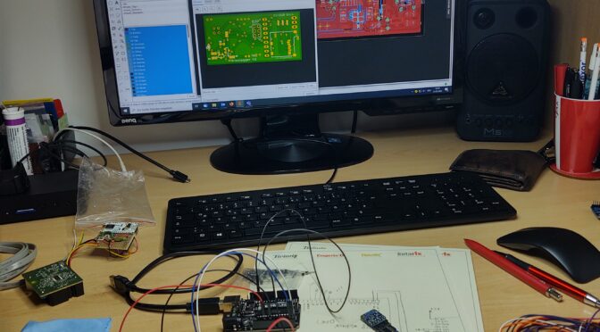
A few years ago I presented a project in which a Raspberry Pi was working as a data logger. A few sensors were connected to this Raspberry, which recorded environmental data such as air temperature, relative humidity, air pressure and the current GPS position. The sensors mostly consisted of ready-made breakout boards that were connected to the RaspberryPi via the various buses (I²C, Serial, SPI …). Python scripts ran on the PI itself, which read out the sensors, summarized the data and stored it on a USB flash memory. I then built this hodgepodge of components into a plastic box with a size of 150x80x50mm.

But it’s also about a lot smaller. As part of a small project, the task was to downsize this sensor / data logger. My approach to realizing this was very simple: “Everything new”. So I changed the concept like this:

  • the RaspberryPi is replaced by a microcontroller
  • a circuit board is created on which all components are housed
  • the recorded data is saved on a microSD card
  • the board is reduced to the most essential components. The sensor electronics and the SD card reader are placed directly on the board
  • a GPS receiver (in the form of a breakout board) should be able to be plugged in as an option
  • the controller is programmed via an ISP interface
  • the power supply is 5V DC

From this I created the following block diagram:

Block diagram

As is so often the case, the central element is the Atmega328 microcontroller. As an external circuit, it only needs a quartz for clock stabilization. (More precisely, it also offers the option of using internal oscillators …) The microcontroller communicates with the sensors HYT939 and BME280 via the I²C bus. The level from 5V on the controller side to 3.3V on the sensor side is adjusted via the sophisticated bidirectional level shifter circuit using a BSS138 Mosfet with an integrated body diode. This circuit is used for both the SCL (Serial Clock) and the SDA (Serial Data) line.

The data is saved on a microSD card. A card slot is installed for this, which communicates with the controller via SPI (Serial Peripheral Interface). An adjustment of the signal amplitudes is also necessary here. This time, however, the TXB0108 chip from Texas Instruments takes care of that. This is an 8-bit bidirectional level shifter.

A button will start and stop data recording and a LED will display various status messages through flashing sequences.

The optional plug-in GPS module works with a 5V power supply and the levels of the serial data communication (RS232) are also 5V compatible.

Last but not least, the power supply must of course also be planned. Only an external, stabilized 5VDC source should be connected here to supply the logger. The 3.3VDC required for the sensors and SD card are generated on the board by means of an LDO (Low Drop Out) controller.

Once all components and their interaction have been defined, the circuit diagram is drawn from them. For my handicraft projects I mainly use the schematic and layout editor “eagle”. The circuit shown below results from the block diagram.

From the circuit diagram I created a layout with two layers, the floor plan of which has the dimensions 55x25mm. Except for the connectors, only SMD components are on the board.

In the layout tool there is the function to view an optical preview of the finished board. In this way you can check in advance whether the board corresponds to the requirements and, if necessary, optimize the position of the components. Once this is done, a package with production files (Gerber files) is generated from the design and this is then sent to the circuit board manufacturer you trust. Since it is also located very, very far away, production also takes a few days. But in the end the circuit boards arrive and are also impressive. 🙂

The two pictures above show the board from the TOP and the BOTTOM side. The next step is to order the components according to the plan and then assemble them.

I do the assembly by hand with a soldering iron suitable for the SMD components with a correspondingly small tip. For the very small parts, such as the BME280 sensor, a microscope or microscope camera is also used.

The two pictures above show what the board looks like after it has been assembled. The following photo shows the size difference of the finished logger with the attached GPS module compared to the old “weather frog”After completing the hardware, it is now time to start with the software. I tinkered it in a practical way with the Arduino IDE tool and flashed it to the controller via AVRISP mk2 via ISP. In order to get the AVRISP to work on a Windows 10 computer, a suitable driver must be installed. (libusb-win32-1.2.6.0 helps here)

program code created with the ArduinoIDE
controller flashed with AVRISPmkII

Data recording is started on the SD card after applying the supply voltage and pressing the button. The measured values ​​are written every second. If, as in this example, the GPS sensor is plugged in, the GPS data is also recorded. The software also records if the GPS sensor does not have a “fix” yet. (Since there was no GPS fix in the example log below, no valid GPS data is included.)

Example of the data log:

Luftdruck962.41
Luftfeuchte37.05
Temperatur26.96
-----------------------------
$PGACK,103*40
$PGACK,105*46
$PMTK011,MTKGPS*08
$PMTK010,001*$GPGGA,235947.799,,,,,0,00,,,M,,M,,*71
$GPGLL,,,,,235947.799,V,N*73
$GPGSA,A,1,,,,,,,,,,,,,,,*1E
$GPGSV,1,1,00*79
$GPRMC,235947.799,V,,,,,0.00,0.00,050180,,,N*48
$GPVTG,0.00,T,,M,0.00,N,0.00,K,N*32
$GPGGA,235948.799,,,,,0,00,,,M,,M

-----------------------------
Luftdruck962.39
Luftfeuchte36.72
Temperatur26.95
-----------------------------
Luftdruck962.43
Luftfeuchte36.66
Temperatur26.97
-----------------------------

Data Node with Arduino

Loading

Unfortunately, the intervals in which I find some time to write a new post for the blog have not gotten shorter. But post a post per month, I think … 🙂

This time it’s not a retro craft project from the local Gefielden or a restoration of an old device, but again something about Arduino. The idea – to build a sensor that, as always, transforms a physical quantity into an electrical signal. This is nothing special and what kind of sensor it will be, I will not describe for the time being. But there should not be a sensor board, but many. And these sensor boards short “sensors” are to be networked together in a two-dimensional matrix. You can imagine it as a chessboard, with each of the chessboard panels representing a sensor. This network of sensors – ie sensor nodes – should then be connected via a transfer point to a computer and output the sensor data of the respective field. It should then also be possible to remove individual fields from the network without the remaining network losing its function.

The whole system should be as simple and cheap as possible. And so a system concept was quickly developed in which the nodes communicate via the I²C bus and send their data to a master. The following diagram is intended to illustrate this.

This concept, I thought, is easiest to implement with an ATmega microcontroller. The has enough IO’s, an I²C bus and UART onboard, as well as analog inputs and requires little component peripherals to bring it to life in its own layout. And there is nothing faster to do such a test setup of such a node network than to use the well-known Arduino development boards. I have chosen the cheapest version for a test setup -> the Chinanachbau of the ArduinoUno (Joy-IT UNO) with the Atmga328 in the capped DIL housing.

Joy-It Uno Boards

The picture shows ten of these microcontroller boards. Of these, one should be used as a bus master and nine as slaves. Of course, each of these slaves has a unique bus address, which only occurs once in the system. In the test setup, this bus address is permanently assigned via the program code, since anyway each Arduino must be connected to the computer in order to carry out the program upload. Of course, that should look different later. Because the Arduino is on the Atmega328 chip, its quartz and the few resistors reduced on the sensor board with gelayoutet. The chip should then be programmed via the ISP pins. Of course, as many boards do not always customize the program code and they all have the same Flash file, I want to set the sensor address with a 7-bit DIP switch. A 4021 Cmos Static Shift Register is supposed to read the bits after the controller is powered on and push them serially into the controller. The resulting value is then available as a bus address in a variable.

Each of these slaves with their individual bus address is now queried in sequence by the master node, which state it has and whether it should switch an output or not. That is, the node has only one DO (digital output) with which it can, for example, turn an LED off and on and interrogate one or more DIs (digital input) which polls a state, for example a simple switch. These functions are stored in 2 bits of a byte. Another byte is used to transfer the bus address. So two bytes are sent over the bus. The picture below shows the test setup with the “UNO boards”

All Arduinos are connected to I²C data bus and power supply

The process is as follows:

MASTER:
The master node sends a request after the series to all slave addresses and a switch command (which comes from all nodes of a TEST push button input on the master) for the LED output of the node and sees if a response comes back or not. If no answer comes, the node is not in the network or is defective. If there is an answer, this consists of the address of the node and its status byte. This information is transmitted via an RS232 terminal to the computer connected to the master. Thus, for example, the switching status of each individual node can be displayed on the screen via a visualization using (NI LabView, or Matlab or similar). By adapting the master program, it is also possible to switch the LED outputs of the slaves via the computer.

SLAVE:
When the master node requests data from the slave, the slave sends back two bytes. Where byte0 again is the slave ID (ie bus address) and byte1 is the data. Byte1 actually consists of only two bits encoded as follows (in decimal representation):
 0 = LED off| Sensor not triggered
 1 = LED on | Sensor not triggered
 2 = LED off | Sensor triggered
 3 = LED on | Sensor triggered

The program code as an example:

 1
 2
 3
 4
 5
 6
 7
 8
 9
10
11
12
13
14
15
16
17
18
19
20
21
22
23
24
25
26
27
28
29
30
31
32
33
34
35
36
37
38
39
40
41
42
43
44
45
46
47
48
49
50
51
52
53
54
55
56
57
58
59
60
61
62
63
64
65
66
67
68
69
70
71
72
73
74
75
76
77
78
// I2C Slave Code
// 16.05.2018 
// ver 1.3
#include <Wire.h>
#define ADDRESS 2     // adresse des slave knotens
#define PAYLOAD_SIZE 2 // anzahl der bytes  die vom masterknoten zu erwarten sind
int LED=12;            // indicator led an pin D12
int SENSOR = 8;        // sensor input an pin D8
bool actionState=0;      // sensor zustand
int busstatus;  // statusvariable 
                       // 0 = LED aus | sensor nicht belegt
                       // 1 = LED ein | sensor nicht belegt
                       // 2 = LED aus | sensor belegt
                       // 3 = LED ein | sensor belegt
 
bool sensled=0;          // sensor LED
byte nodePayload[PAYLOAD_SIZE];

void setup()
{
  pinMode(LED, OUTPUT);         //sensorLED
  pinMode(SENSOR, INPUT);       //Sensor 
  Wire.begin(ADDRESS);          // Activate I2C network
  Wire.onReceive(receiveEvent);
  Wire.onRequest(requestEvent); // auf master anforderung warten
                      //  // debug interface
                      //  Serial.begin(9600); 
}

// *********************************mainloop****************************************************
void loop()
{ 
  delay(5);
  
   if(sensled){digitalWrite(LED, HIGH);}
         else{digitalWrite(LED, LOW);}

  actionState = digitalRead(SENSOR);  //Sensoreingang abfragen        
   if((actionState==1)&&(sensled==1)) {busstatus=3;}
   else if ((actionState==0)&&(sensled==1)) {busstatus=1;}
   else if ((actionState==1)&&(sensled==0)) {busstatus=2;}
   else if ((actionState==0)&&(sensled==0)) {busstatus=0;}

                      //  Serial.println("######################");
                      //  Serial.print("busstatus neu setzen ");
                      //  Serial.println(busstatus);
                      //  Serial.print("sensled LED            ");
                      //  Serial.println(sensled);
                      //  Serial.print("actionState           ");
                      //  Serial.println(actionState);
                      //  Serial.println("######################");
  nodePayload[0] = ADDRESS;                  // Adresse in byte0 zurücksenden.  
  nodePayload[1] = busstatus;                //byte 1 ist die statusinfo der LED
}


// *********************************************************************************************
void requestEvent()
{ Wire.write(nodePayload,PAYLOAD_SIZE);  
  Serial.println("bytes status schreiben");
  Serial.println(nodePayload[0]);
  Serial.println(nodePayload[1]);
  delay(5);
}

// *********************************************************************************************
void receiveEvent(int bytes)  //einen wert vom I2C lesen
      
{
  
  busstatus = Wire.read(); //If the value received was true turn the led on, otherwise turn it off  
                              //  Serial.println("status empfangen");
                              //  Serial.println(busstatus);
  if((busstatus==1)||(busstatus==3)){sensled = 1;}
                                else{sensled = 0;}
                                              
}


The bus address must still be entered individually in this slave code. In the next version, the previously described “serializer” of the parallel dip-switch variant will be implemented. The following code example is from the master node, which reads out the slaves and sends a LED pattern to the sensor slaves using the test button:


  1
  2
  3
  4
  5
  6
  7
  8
  9
 10
 11
 12
 13
 14
 15
 16
 17
 18
 19
 20
 21
 22
 23
 24
 25
 26
 27
 28
 29
 30
 31
 32
 33
 34
 35
 36
 37
 38
 39
 40
 41
 42
 43
 44
 45
 46
 47
 48
 49
 50
 51
 52
 53
 54
 55
 56
 57
 58
 59
 60
 61
 62
 63
 64
 65
 66
 67
 68
 69
 70
 71
 72
 73
 74
 75
 76
 77
 78
 79
 80
 81
 82
 83
 84
 85
 86
 87
 88
 89
 90
 91
 92
 93
 94
 95
 96
 97
 98
 99
100
101
102
103
104
105
106
107
108
109
110
111
112
113
114
115
116
117
118
119
// I2C masterknoten 
// 16.05.2018 
// ver 1.2
// changes abfrage wenn kein knoten am bus dann 255 ausgeben
#include <Wire.h>

#define busbytes 2          // wievele byte vom I2C knoten zu erwarten sind
#define maxKNOTEN  10       // anzahl der zu scannenden slaves
#define startKNOTEN 2       // startadresse der slaves
#define DELAY 5             // einfach ein delay ....

int i; int j=0;
int buttonPin = 12;
int testbut = 0; int anim = 0;
int buttonState = 0;
int DATEN[busbytes];
int adresse; int busstatus;  
byte sensorbelegt; byte ledsensoron;

                       // 0 = LED aus | Sensor nicht belegt
                       // 1 = LED ein | Sensor nicht belegt
                       // 2 = LED aus | Sensor belegt
                       // 3 = LED ein | Sensor belegt

int leddat1[] = {1,1,1,1,0,1,1,1,1}; // -
int leddat2[] = {0,0,0,0,1,0,0,0,0}; // |

void setup()
{
  Serial.begin(9600);  
  Serial.println("MASTER-KNOTEN");
  Serial.print("Maximum Slaveknoten: ");
  Serial.println(maxKNOTEN);
  Serial.print("Datengroesse in byte: ");
  Serial.println(busbytes);
  Serial.println("***********************");
  
  Wire.begin();                 // Activate I2C link
  pinMode(buttonPin, INPUT);    // test-tastereingang festlegen
}


//#####################################################################################################
void loop()
    
{
  for (int Knotenadresse = startKNOTEN;         //alle knoten scannen
           Knotenadresse <= maxKNOTEN; 
           Knotenadresse++) 

        
    //################################################################################################       
    { 
     // testbut = 0;  
     anim = 0;   
    Wire.requestFrom(Knotenadresse, busbytes);        // daten vom jeweiligen knoten anfordern
                                                 
           DATEN[0]=255; DATEN[1]=255;   // wenn kein knoten dann auf 255 setzen    
          if(Wire.available() == busbytes) {                                    // wenn knoten und daten dann
            for (i = 0; i < busbytes; i++) DATEN[i] = Wire.read();          // daten holen (zuerst busID, dann daten)
           // for (j = 0; j < busbytes; j++) Serial.println(DATEN[j]);        // daten an rs232 ausgeben   
          }            

//            Serial.println(Knotenadresse);
//            Serial.println(DATEN[0]);
//            Serial.println(DATEN[1]);
//            Serial.println(" ");
           
            adresse=DATEN[0]; 
            busstatus=DATEN[1];
           
            if(busstatus == 0)       {sensorbelegt=false;  ledsensoron=false;}
            else if (busstatus == 1) {sensorbelegt=false;  ledsensoron=true;}
            else if (busstatus == 2) {sensorbelegt=true;  ledsensoron=false;}
            else if (busstatus == 3) {sensorbelegt=true;  ledsensoron=true;}
      
         //################################################################################################
         //Testbutton Status lesen und variable testbut entsprechend setzen
       
          buttonState = digitalRead(buttonPin);               //tastereingang einlesen
          if(buttonState == HIGH){                            //wenn taster aktiv dann variable anim setzen
          anim = 1;
          //delay(5); 
          }
            
//            //debug debuginfo tasterstatus auf rs232 ausgeben
//            Serial.println("#######################");
//            Serial.print("Knoten Adresse    :");
//            Serial.println(adresse);
//            Serial.print("Busstatus         :");
//            Serial.println(busstatus);
//            
//            Serial.println("----------------");
//            Serial.print("Fliese belegt    :");
//            Serial.println(sensorbelegt);
//            Serial.print("LED Fliese       :");
//            Serial.println(ledsensoron);
//            Serial.print("#######################");
//            Serial.println(" ");
      
          //################################################################################################
          //Testbutton Status an jeweiligen knoten senden
      
          Wire.beginTransmission(Knotenadresse);           // transmit to device actual in for loop
          //anim schreiben
                    
           if (anim==0) {testbut=leddat1[j]; j++;}
                   else {testbut=leddat2[j]; j++;}
           if (j>8){j=0;}
          
          Wire.write(testbut);                             // senden des tasterstatus
          Wire.endTransmission();                          // ende gelände mit uerbertragung
       
          delay(DELAY);
          

    }
   
}


With this arrangement, it is now possible to read all Arduinos and their input or to control the LED via the bus. In the next step, a “sensor” is built, a board is laid out and the ArduinoUno reduced to its microcontroller. I’ll talk about that in one of the next posts …