
Keysight DSO-X 2012A oscilloscope dies in standby – power supply replacement
![]()
In an old post from 2019 I reported about oscilloscopes from the manufacturer Keysight and their problem with a sudden failure. (see link). At that time, it was about oscilloscopes suddenly refusing to work – sometimes with a bang and subsequent smell of “power”. Or simply nothing happened at all after switching on. The reason was and is always the failure of the installed 12VDC power supply CCH0123F1-Z03A. The oscilloscope is designed in such a way that the power supply is still connected to the mains when the “main switch” of the oscilloscope is switched off and is operated in standby mode. The push button switch located on the front panel of the unit then switches the power supply into PowerON mode and 12V power on.
If the devices in the laboratories are permanently connected to live sockets, it is not surprising that the devices age faster than the good old boxes with the cathode ray tubes. The parts, which fall victim to the permanent power supply by thermal continuous load, I have, as well as also the repair expenditure in the contribution at that time represented. On the part of the distributing companies also a reordering or a replacement delivery of new power supplies is not intended or desired. If the devices fail within the warranty period, the replacement by the manufacturer is no problem. If the devices fail after a few years in the laboratory or workshop (it doesn’t matter if they are in use every day, or just stand around plugged in and switched off), then a normal repair service process is carried out by the manufacturer. There are then also the proper tariffs for the service of measurement technology to pay.
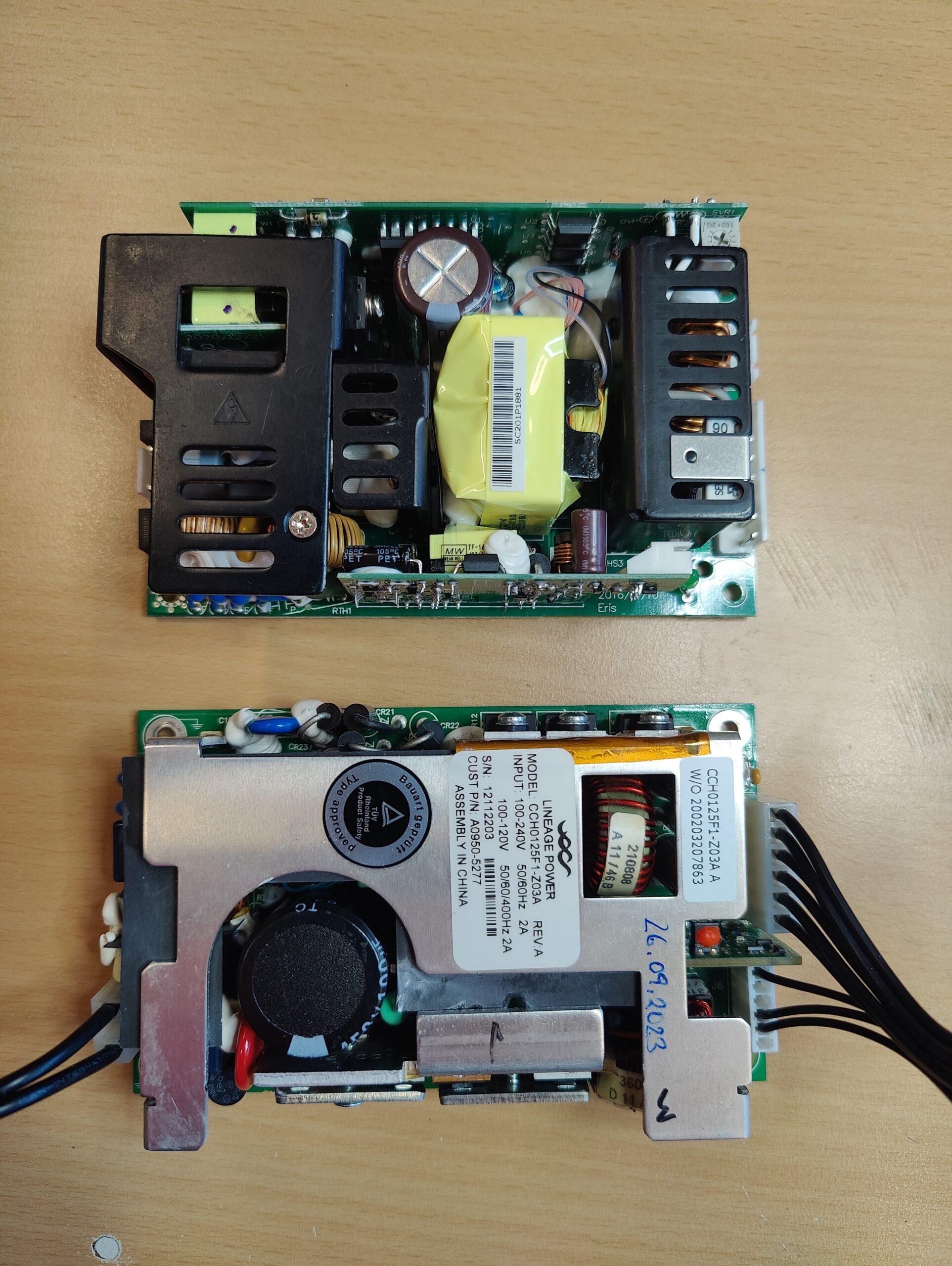
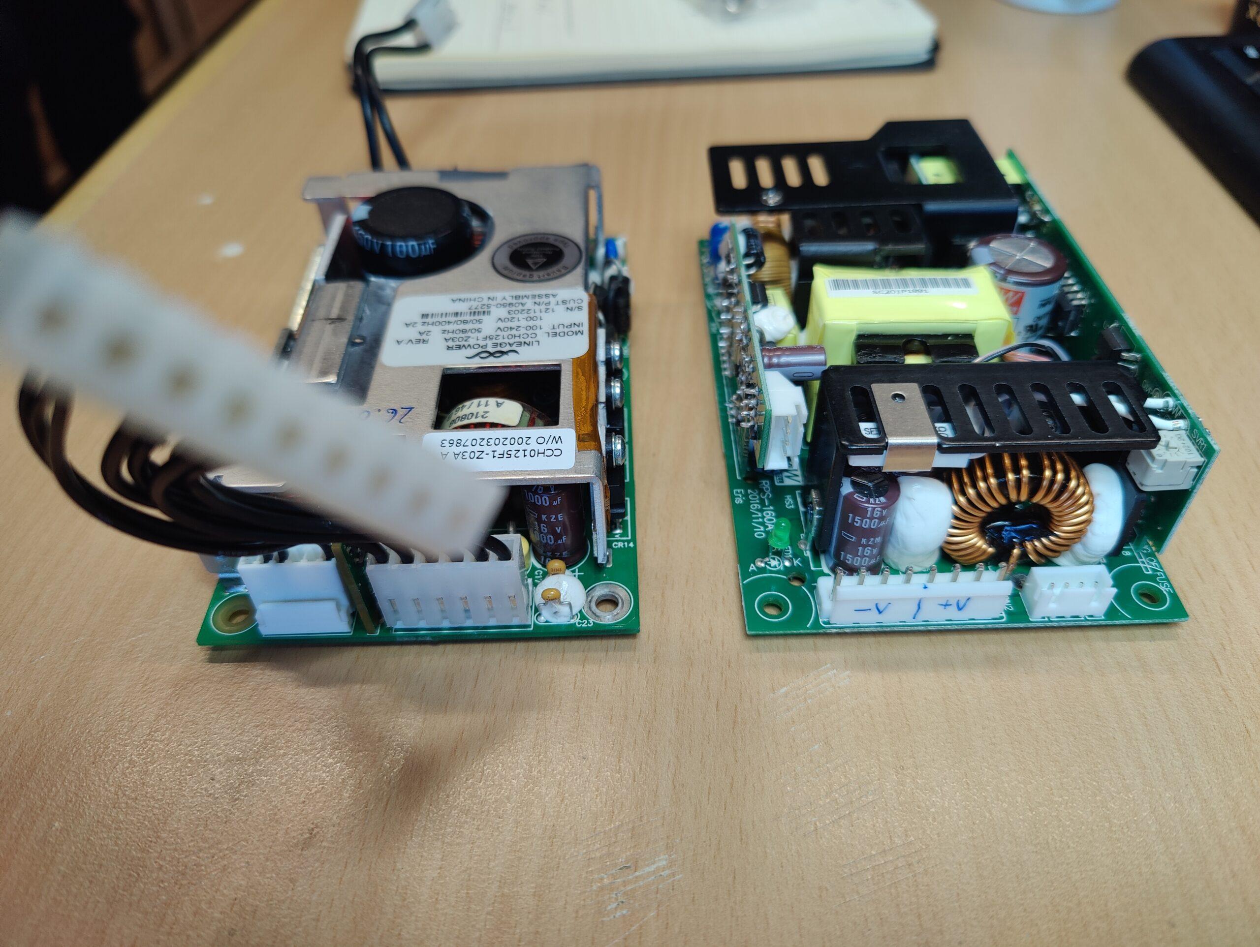
In the picture above: “new Meanwell Powersupply” below: “original Lineage Power”.
The power supplies are quite easy to repair, as described in the old report. However, the repair is also quite time-consuming. Of course, it is faster to install a new power supply. Unfortunately, the distributors of the Keysight oscilloscopes do not offer spare parts support and I could not find a direct supplier of the original Lineage power supply. But there is another alternative: In the forum of the EEV blog some users have found alternative power supplies that fit into the DSO-X oscilloscopes. A suitable model is the RPSG-160-12 from Meanwell. It is a 12V 160W power supply. The designation “G” in RPSG indicates that there is also a 5V standby supply. And it is exactly this function that the DSO-X needs. Because as described before, the front switch on the osci is not intended to disconnect the primary side of the mains supply, but only to switch a line on the DC low voltage connector to ground. This line controls the “PowerON pin” in the power supply.
Mechanically, the Meanwell almost fits on the mounting brackets of the DSO-X. “Almost” means that the distance between the mounting holes of the long side on the powersupply is about one millimeter further apart than the mounting bolts on the chassis of the oscilloscope. However, this can be quickly adjusted with a small round file or a 4mm drill bit. Now the Meanwell Powersupply can be attached to the oscilloscope chassis with the original Torx screws. The plug connection for the AC supply from the OSZI board to the power supply can be taken directly from the old power supply.
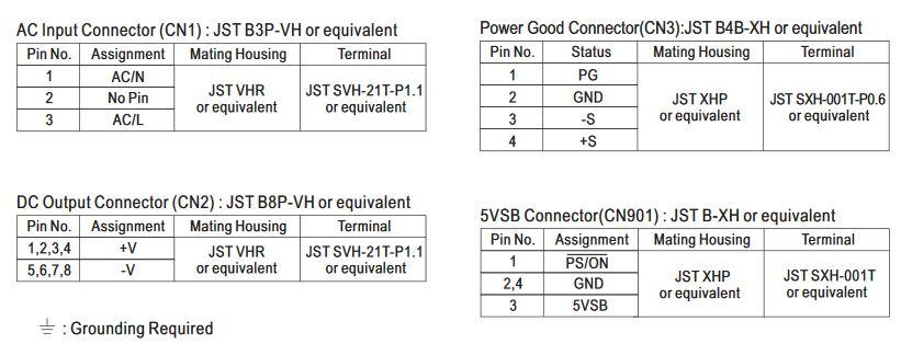
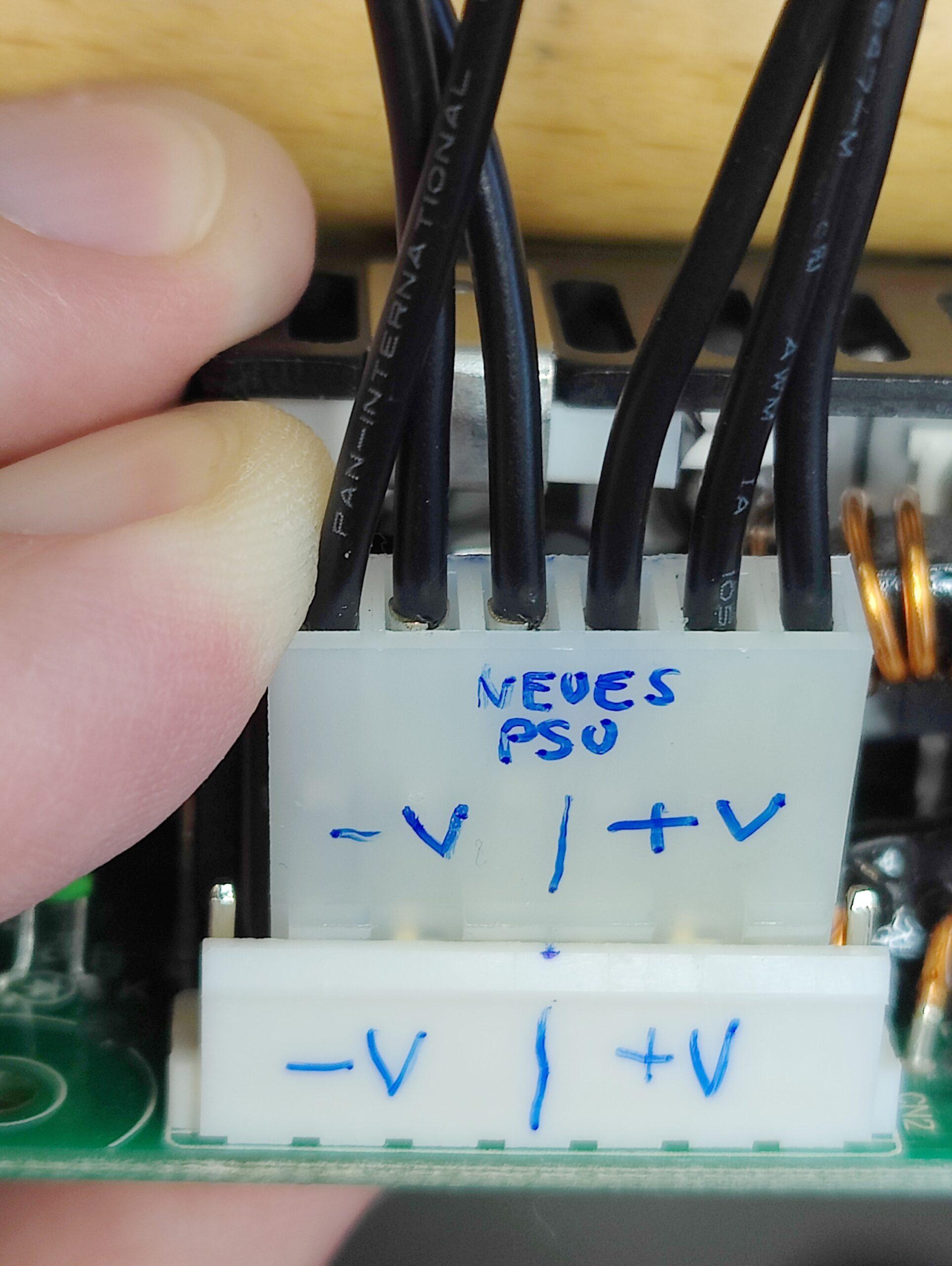
Pinout of the Meanwell connector strips
The 12V voltage supply at CN2 of the power supply is connected to pins 1,2,3,4 (+12V) and 5,6,7,8 (GND). The connection line to the oscillator must be adapted accordingly.
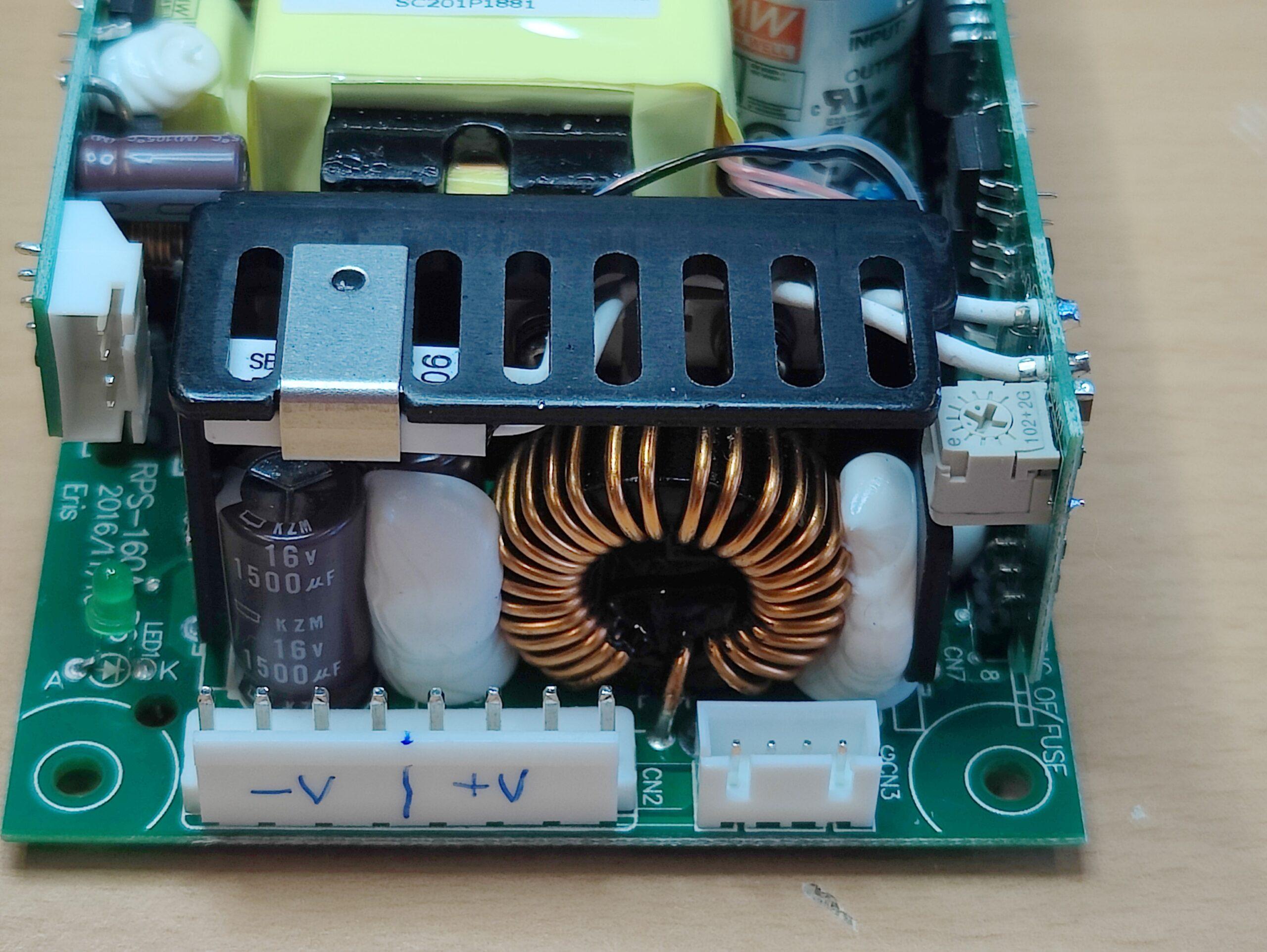
DC12V outputs on CN2
The picture below shows the pins of the connector strip on the oscilloscope labeled.
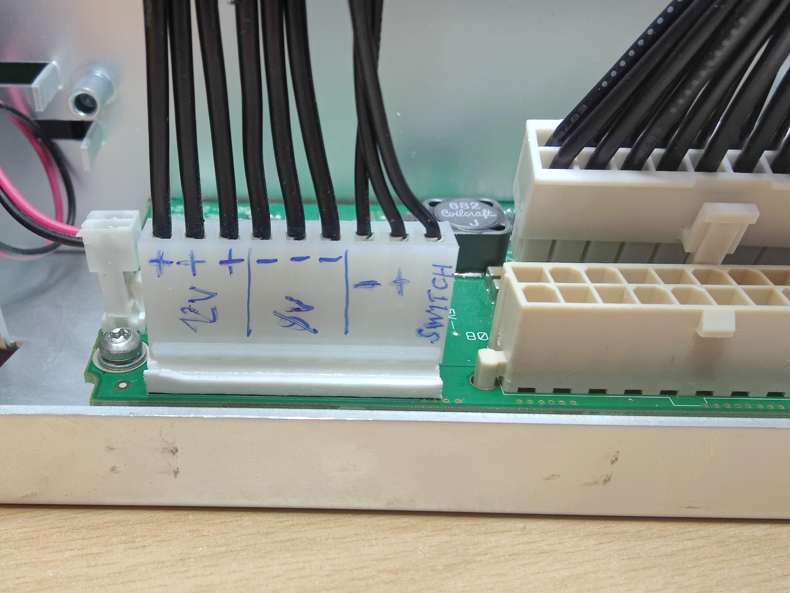
DC12V input to oscilloscope
I re-pinned the wires to fit and connected the connector to the powersupply as shown below.
 The main power supply to the oscilloscope is now established. Only the “power-on line” (PowerOn) is missing. For this I disconnected the 7th pin (GND) and the 9th pin (Switch) from the old connector and soldered them directly to the standby board of the power supply. The wire at the lowest pin of the standby board is the signal “PowerOn” and the one above is GND. So the power supply can be powered up with the front power switch on the oscilloscope.
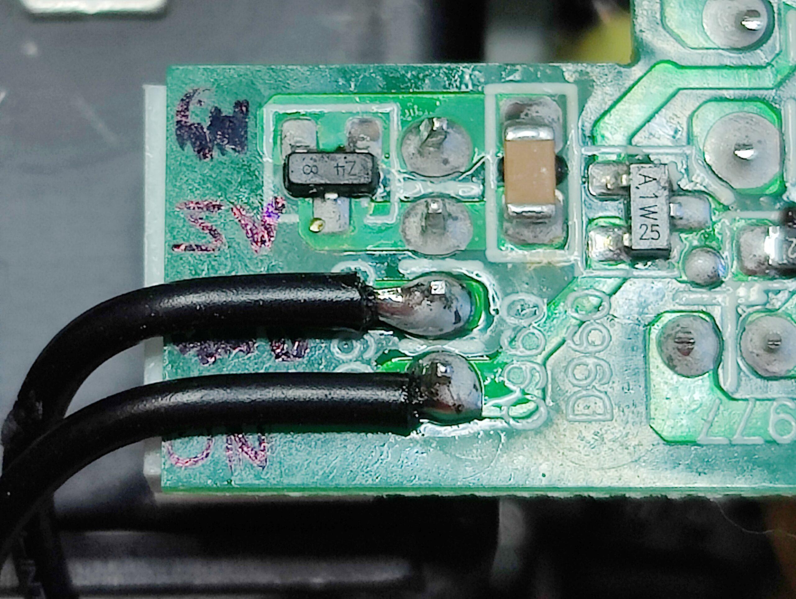
“Control lines” for the PowerOn of the power supply unit
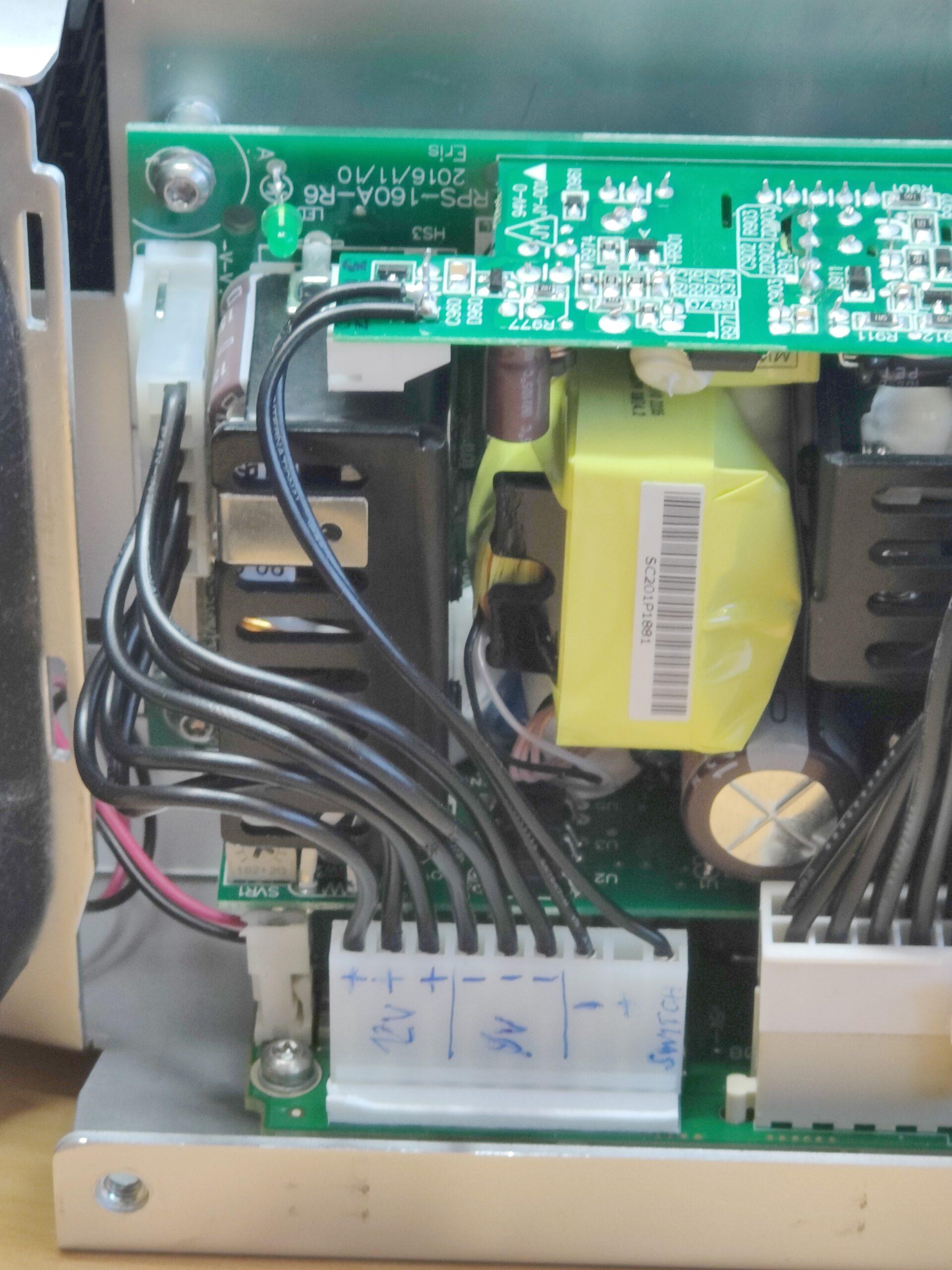
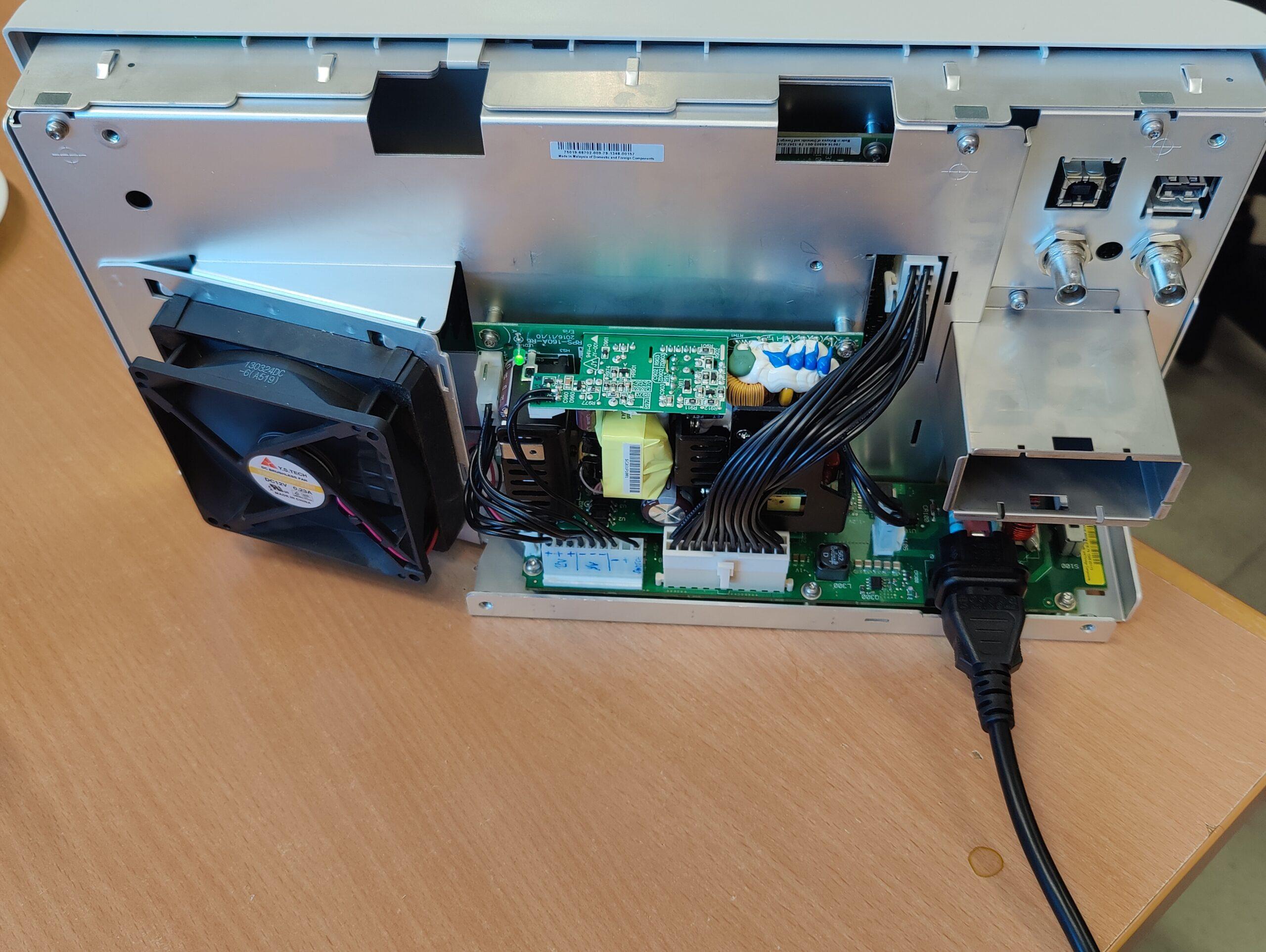
General view of the wiring
After a short function test and checking of the voltage (can be corrected if necessary also at the trim potentiometer at the power supply) the rebuilding is finished and the assembly can take place again.


2 Responses
Many thanks for this: Keysight DSO-X 2012A oscilloscope dies in standby – power supply replacement.
I fixed 2 MSO-X-3034A with a replacement supply.
So it also works for those, in case anyone doubts..
A shame actually that so such an expensive oscilloscope has this kind of crappy supply!
For that reason(and money/value ratio) we moved towards R&S RTM3000/RTA4000 series in full options config.
Really a joy to work with those!
Thank you so much for this excellent tutorial on the power supply. I have just replaced two and they are going strong plus, I have a couple of dozen in our work area that I will monitor. It’s a shame the unit shuts off the fan and the display, but leaves the supply running to bake the capacitor. We replace all of the capacitors we could, but two power supplies were beyond saving.