
Neumann KH-120 mystery noise fix
![]()
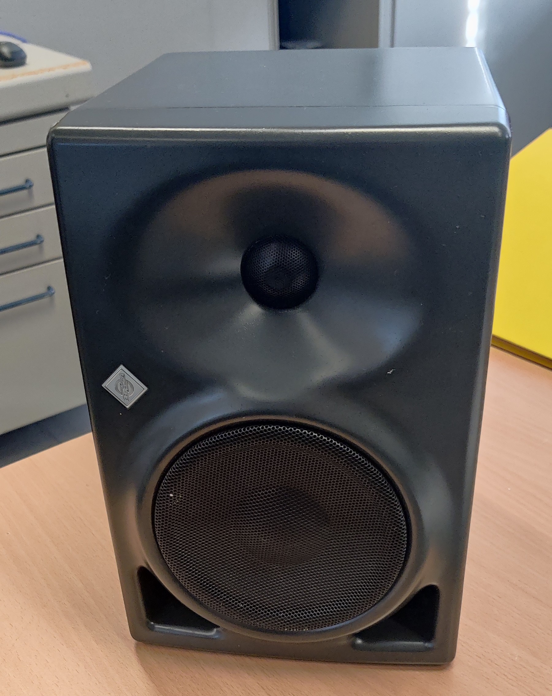
This time, a defective pair of active speakers found me, which comes from the professional corner of sound generating devices. These devices also occasionally have problems or fail. If you do a little research in the forums on the Internet, the KH-120 boxes are very robust and durable. The only issues I’ve read about are power supply failures. Occasionally there are also reports of a clear noise or whistling even if no signal is applied.
Exactly this problem was shown by these devices. After switching on, there was a hissing noise up to slight whistling tones. These could be influenced with the filter and gain switches, but not remedied. If the loudspeakers were in use for a long time – after about half an hour, then the noise decreased.
Unfortunately I didn’t manage to find useful information about these errors on the net, let alone a circuit diagram of the board. So there is nothing left but to search for it yourself, analyze the board and search systematically for the error.
Starting with the removal of the four long Allen screws, the two halves of the housing can be carefully pulled apart. This then reveals two white blocks of insulation. These can easily be removed. The wire connection to the loudspeakers can be detached from the circuit board using a four-pole plug. Likewise the connection to the small LED logo board.
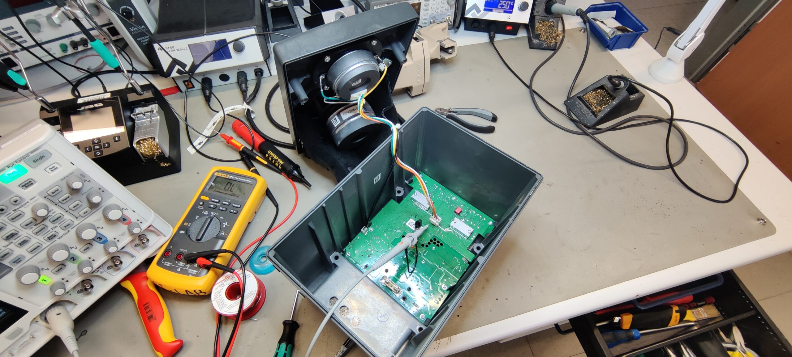
KH-120 is open and the insulation material removed
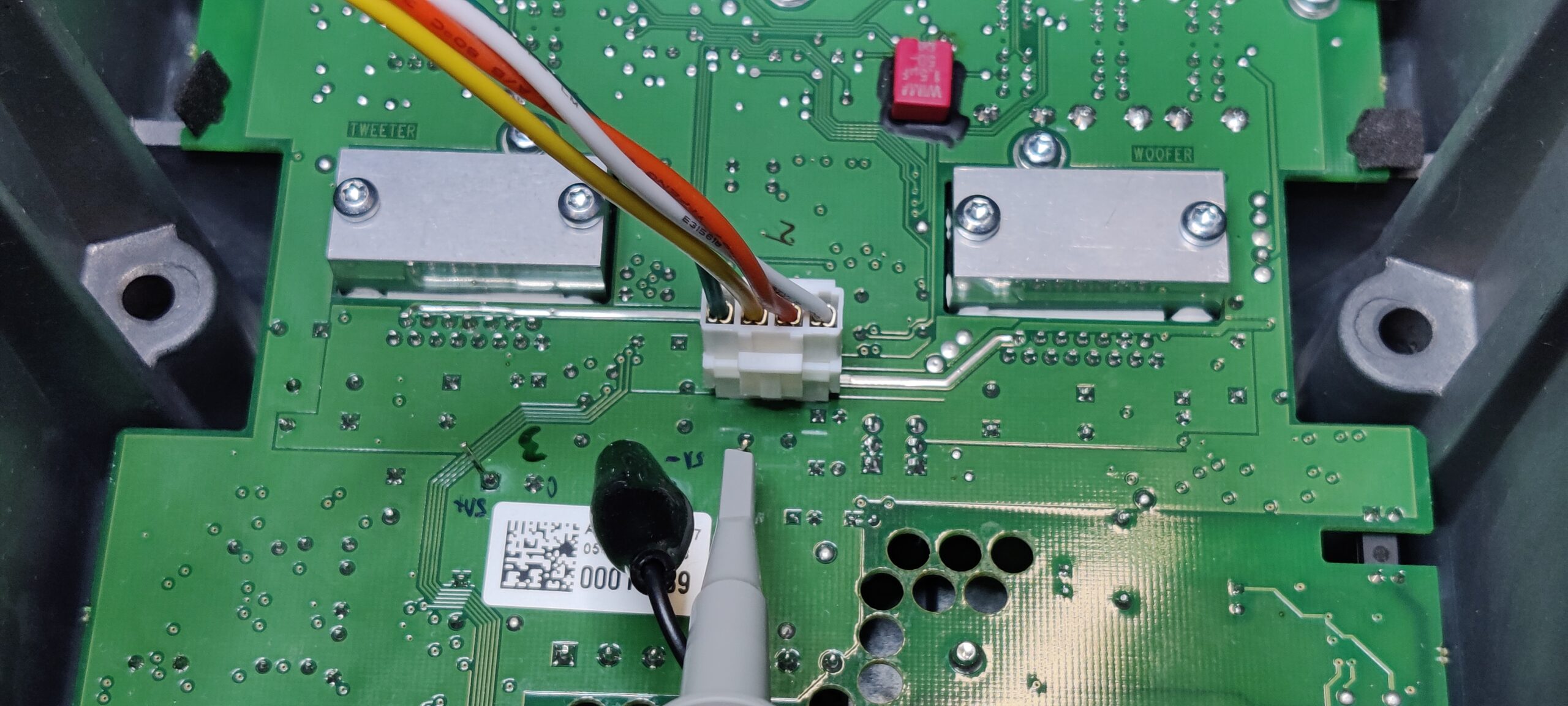
The picture shows the connector with the wires to the speakers
Next, the circuit board can be unscrewed from the housing. (a Torx bit is to be used here) All screws except for the two black cross-head screws must be loosened. Then carefully remove the board from the housing.
Circuit board of th Neumann KH-120
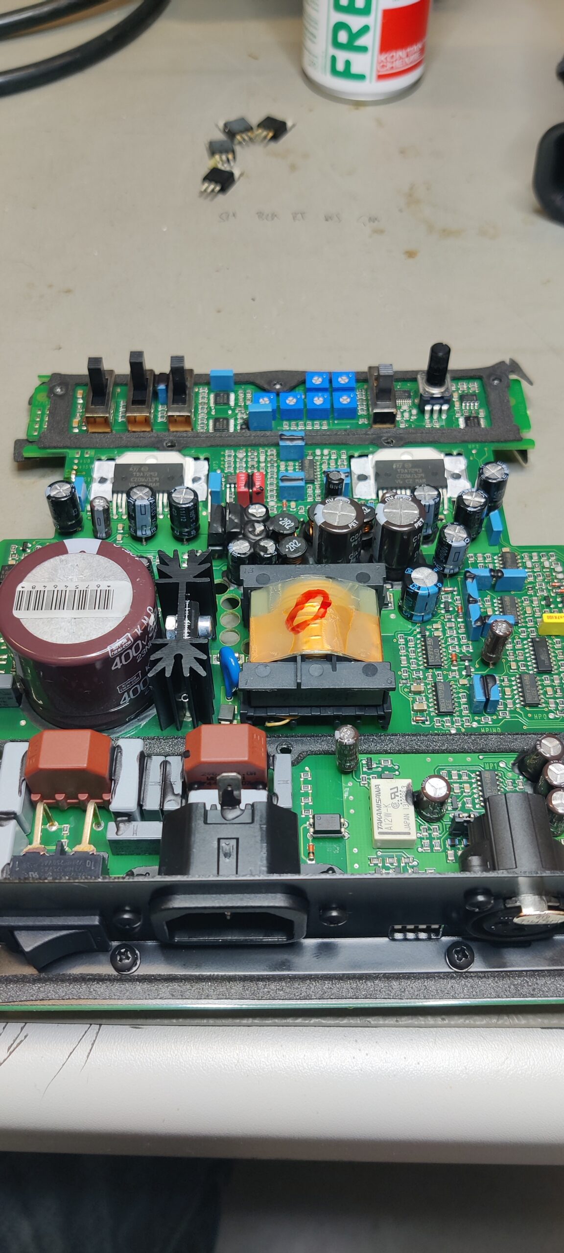
The board looks very good. All components that can be set into mechanical vibrations and possibly resonance by the sound are secured with elastic adhesive. The board layout is nice and clear. You can see the mains input and the mains filter at the bottom left of the picture. Above it is the large electrolytic capacitor for smoothing the direct voltage generated from the mains voltage.
The power supply is a switching power supply. The Mosfet controlled by a controller chip clocks the transformer. On the secondary side it is rectified again and the symmetrical voltages +Ub and -Ub for the power section of the output stages, as well as +15V and -15V for the supply of the pre-amplification and signal processing are generated. Ub is at -42 or + 42V. The power output stages are two TDA7293 ICs. One controls the tweeter and the other controls the woofer.
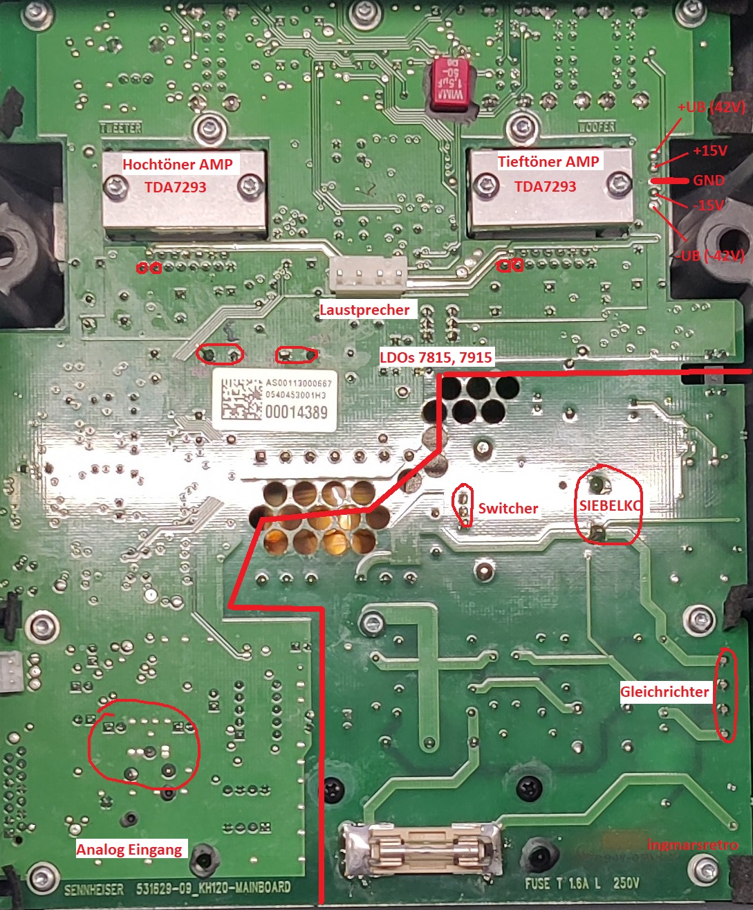
backside of the circuit board
In order to look for the cause of the problem, one proceeds systematically. I first checked the supply voltages with a multimeter. Of course they are there. But you only see the truth when you look at it a little more closely. The multimeter is no longer sufficient here. An oscilloscope also reveals the AC component or residual ripple.
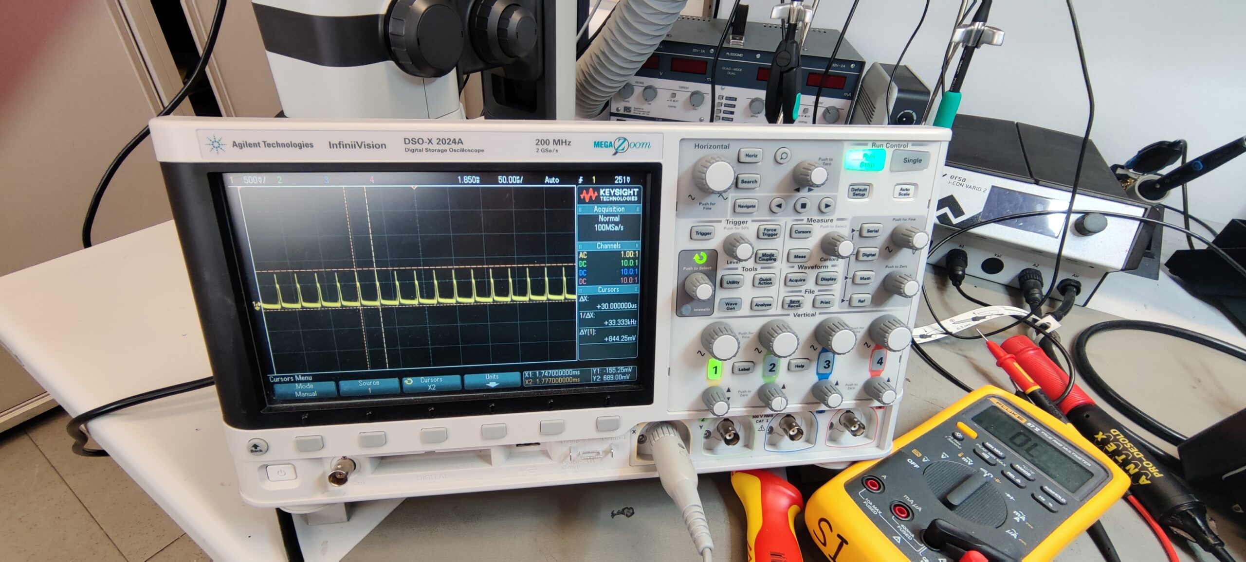 The picture shows the AC part of the -15V power supply. At around 800mV, however, it is suspiciously high. The period duration of these peaks with 30µs indicates that the transformer is regulated when the power supply unit hardly has to deliver any power. The switching frequency of the transformer can be seen within the pulses. But what could still be seen and cannot be seen in the still image are lower-frequency, asymmetrical components with an equally high amplitude. Accordingly, there appears to be a problem with smoothing the stress. So I examined the structure of the -15V supply. And look, the +/- 15V are implemented with a series regulator. A 7815 controller is used for the + 15V and a 7915 controller in the TO220 housing for the -15V. In the Note application, capacitors to ground are specified for the IC at the input and output. And that’s exactly what I took a closer look at first. An electrolytic capacitor with 100µF / 35V and 105 ° is used at the input of the 7915. This capacitor had to go out to measure. Immediately after the removal, it seemed to me that the weight of the component was too light – it didn’t feel like anything. So get to the LCR bridge and lo and behold, the capacity was somewhere around 1.4µF.
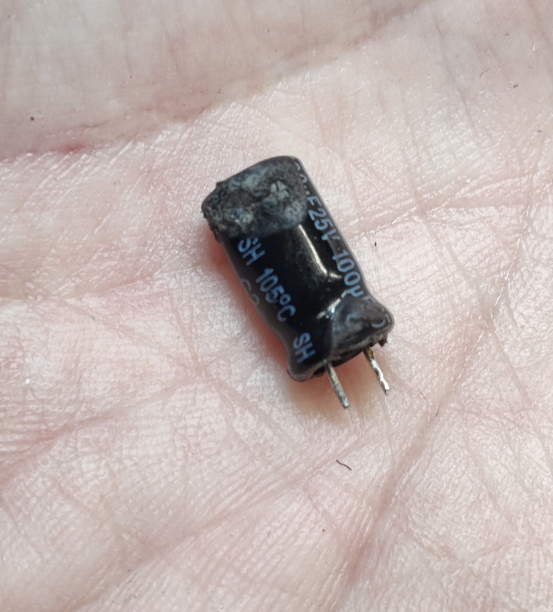
the polluter
A new electrolytic capacitor was installed quickly and the renewed measurement of the voltages revealed a nice signal again. The AC share was now much lower and the irregular disturbances had disappeared. Only the switching of the transformer could still be seen. What was still noticeable, or no longer noticeable, were the noises from the loudspeakers – the noise was gone.
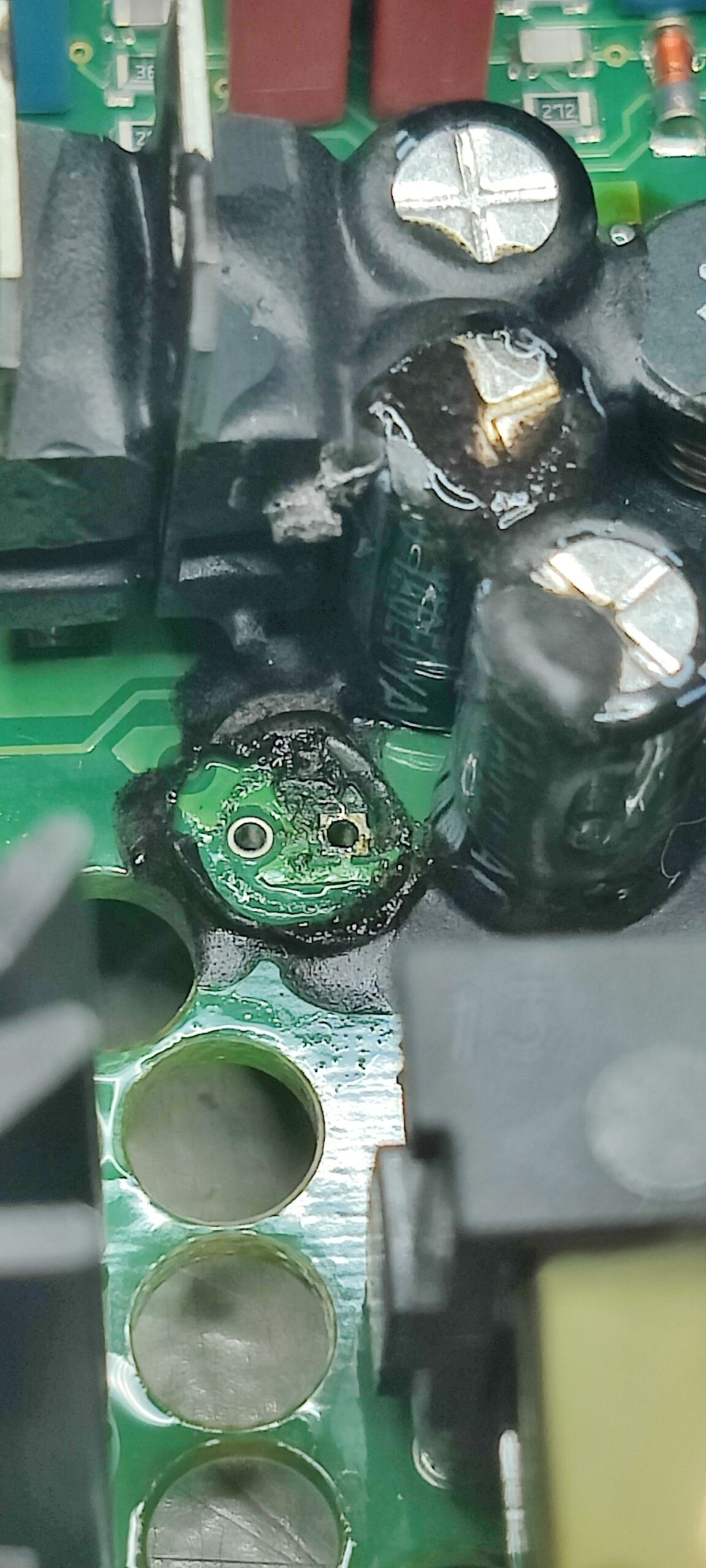
the cause was built in here


4 Responses
I knew it
Hi,
Thank you for your well explained post.
I had the same problem, and I solved it, with your way.
Thank you indeed again.
Hello. Can I as you about my problem with 120kh please?
Hi,
I use kh120 AG US. Suddenly one speaker started
Flashing red & like a pulse. I switched off but it still flashed n slowly turned off. Then i powered it of n restarted. It sounds just good as before. Today this happened again right after i played first audio. What is the issue u think ? It sounds just normal till now but i’m scared that it might happen again.