![]()
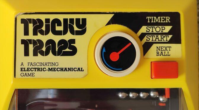
In this post, I’m going to take a look at the restoration – or rather repair – of a handheld game that I recently received for review. It has the name “Tricky Traps”. This means something like “tricky or tricky traps”
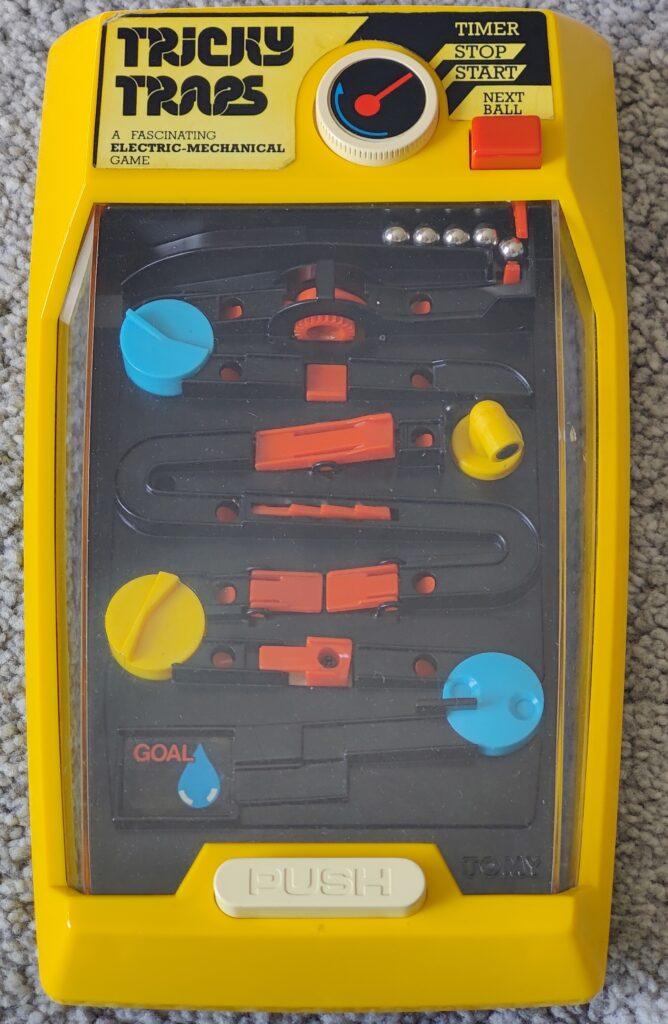
The game “Tricky Traps” by Tomy is a mechanical game of skill that was originally released in the 1970s. It consists of a maze-like playing field in which the player must navigate a small metal ball through a series of obstacles and traps. The aim of the game is to successfully maneuver the ball through the maze to the finish without it falling into one of the many traps. There are five balls available. The game is timed.

Game mechanics:
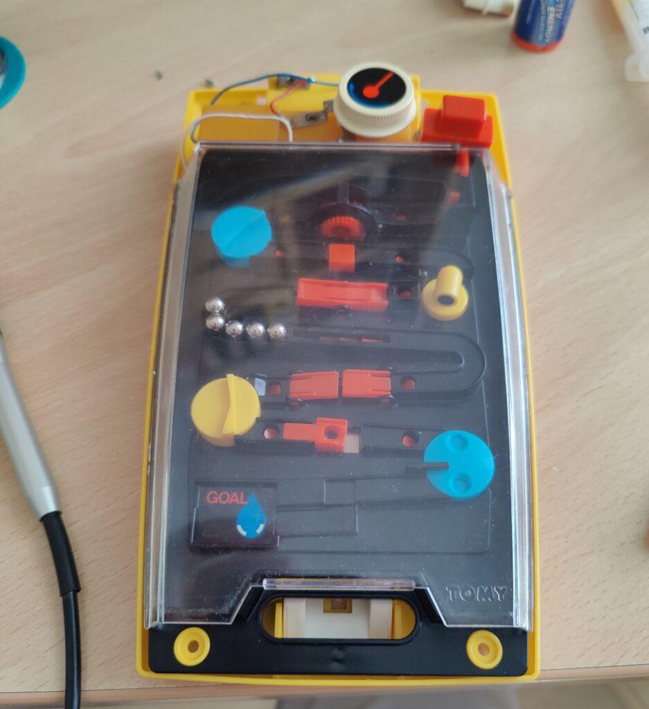
- The player starts the game with a rotary knob, which sets a small electric motor in motion. This motor drives the “traps” and also the rotary knob itself via a gearbox. This is how the “timer” is realized. Once the rotary knob has completed about three quarters of a turn, the motor stops again and the game is over. This is solved by a contact spring, which is pressed down onto a mating contact by a small bar at the bottom of the rotary knob.
- Once the game has started, the red button can be used to release a ball into the track. The white button at the bottom is the actual and only game button. It lifts the ball with a small cylinder so that it can move through the various parts of the playing field. You have to do this with the right timing.
- There are numerous obstacles on the playing field, such as rotating disks, small ramps, narrow passages and a rotating magnet that can stop the ball or cause it to fall into a trap.
The colorful design is typical of the mechanical games of the 70s and 80s. It is made of plastic and the moving parts are usually brightly colored.
The technical problems that occur often in such old games are:
- leaking batteries, which usually cause corrosion and destruction of the contacts
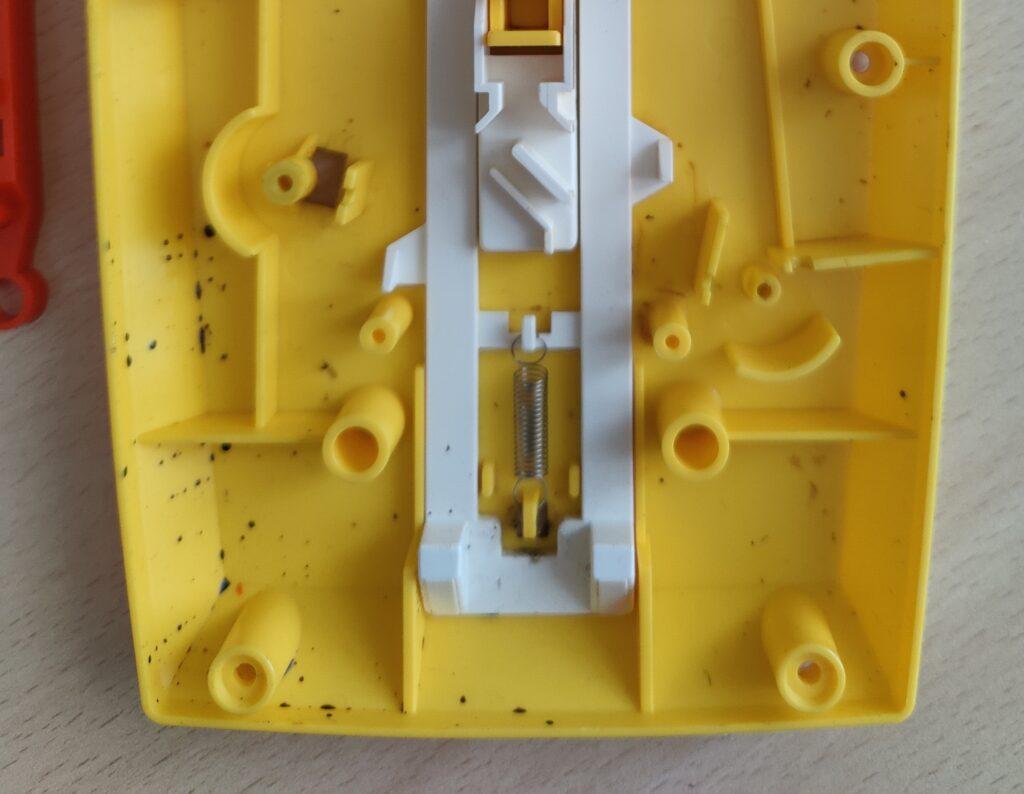
- Brittle plastic, which mainly occurs with gearwheels that are mounted on brass shafts and therefore start to slip. This also means that housing gears often no longer hold together properly.
- Electric motors whose brushes are worn so that they no longer turn
- Resinous grease and oils that make moving parts sluggish
- Wires and electrical connections that are corroded and broken
All of these points can be found very often during restoration and must be fixed. This can also be done more or less easily. After carefully opening and inspecting the appliance, I actually start by completely dismantling and cleaning the parts. Then I try to repair any broken plastic parts. Here I use various adhesives as far as possible. Sometimes it is also necessary to reproduce a part with a 3D printer. Of course, this assumes that enough of the original part is still available to reconstruct it accurately. The electrical components of these devices are the easiest to repair, as there are usually no electronics with any components with ICs that are no longer manufactured.


