![]()
Since I’ve been working on home automation, I’ve naturally wanted to optimize and simplify as much as possible and adapt and implement it in line with the new buzzwords “green electronics”, “sustainability”, “energy-saving” … and so on. For example, my appliances switch off when they are not used or ignored, stand-by energy consumption is largely avoided and IOT technology also prevents human forgetfulness (leaving windows open in winter or forgetting to switch lights off). As readers of the blog already know, I use systems such as HomeMatic, NodeRed and, for some time now, Homeassistant with ESPHome, Zigbee2Mqtt etc. Of course, the aim is also to keep all systems cloud-free. I don’t want the data to take a detour via some server in the Far East to switch a light on and off in my home. So, if possible, everything should take place within my own network and not “phone” to the outside and also work if I cut the data line.
For a long time now, various suppliers have been offering an extremely practical device for comfort in the parents’ quiet room. I’m talking about a space-saving way of accommodating the flicker box (nowadays also known as a flat-screen TV) in the room. I’m just mentioning terms like:
Speaka Professional TV ceiling mount electric motorized (1439178) or MyWall HL46ML … etc. Some of these devices can be controlled with a wireless remote control, others via the Tuya CloudApp. You can bypass the Tuya app via the Tuya IOT development environment and bring these devices into your home assistant via the “TuyaLocal” integration – it works – but it’s more of a “ONLY” solution. In my opinion, the ideal solution is to integrate these devices into the ESPHome system. Using the Speaka Professional TV ceiling mount as an example, I will show you how it can be integrated into the ESPHome network and thus into the Home Assistant with a small extension. This version of the SpeaKa part has no Internet connection and is only controlled via a wireless remote control.

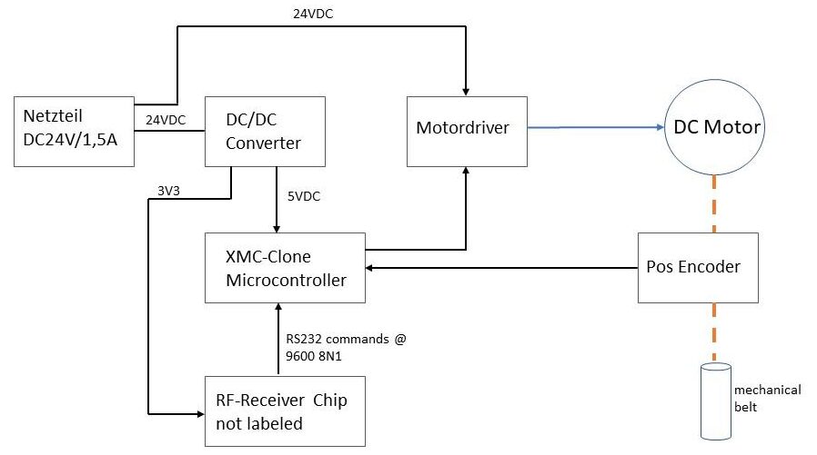
With a little reverse engineering, we (my colleague Werner and myself) analyzed the existing appliance factory. The system is structured something like this:


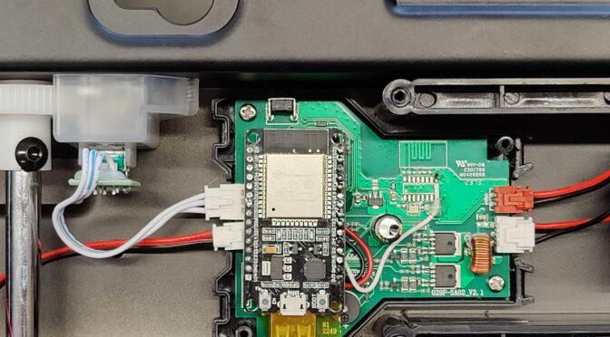
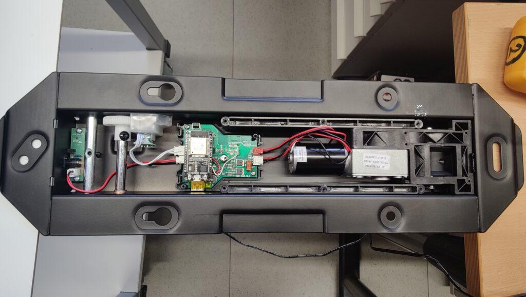
The system diagram above shows how the circuit board is constructed. The power supply comes from a plug-in power supply with DC 24V output at 1.5A. On the board you can still see an unpopulated area whose solder pads are wired with +3V3, GND and RX, TX lines suitable for an ESP8266. A USB socket can also be seen. These two interfaces are not included in the diagram. We examined the RX/TX lines that are routed from the unpopulated solder pads (ESP8266) to the microcontroller (1301 X 016B). However, no signals could be measured here. (Presumably the interface is not activated in the flashed program version).

So this does not take us any further. In the next step, we looked at where the control signals of the radio remote control come from and how they are subsequently implemented. The RF receiver chip has 16 pins and unfortunately no labeling. Or has it been removed? The supply voltage of the RF chip is connected to pin 1 and pin 16, pin 2 and pin 3 are connected to a crystal and a line is routed from pin 9 to the microcontroller. So this must be the data output. Using the “PulseView” software from Sigrok and a Far East logic analyzer, we sniffed this output. And lo and behold, data packets with a duration of 10.3ms were revealed here. The PulseView software was able to recognize the protocol as an RS232 protocol after a few attempts with different analyzed data rates. It was then easy to log the received and decoded control commands to the microcontroller.

The baud rate of the RS232 port on the RF chip output is 9600 at 8N1. 10 bytes are received in HEX for each command sent. Here is the list of commands: (missing bytes follow…maybe sometime)
| Befehl | Byte0 | Byte1 | Byte2 | Byte3 | Byte4 | Byte5 | Byte6 | Byte7 | Byte8 | Byte9 | ||
| UP | 0xAA | 0x06 | 0x04 | 0x25 | 0x03 | 0xD5 | 0x01 | 0x00 | 0x02 | 0x55 | ||
| DOWN | 0xAA | 0x06 | 0x04 | 0x25 | 0x03 | 0xD5 | 0x00 | 0x10 | 0x11 | 0x55 | ||
| LEFT | 0xAA | 0x06 | 0x04 | 0x25 | 0x03 | 0xD5 | 0x55 | |||||
| RIGHT | 0xAA | 0x06 | 0x04 | 0x25 | 0x03 | 0xD5 | 0x55 | |||||
| BUTTON1 | 0xAA | 0x06 | 0x04 | 0x25 | 0x03 | 0xD5 | 0x55 | |||||
| BUTTON2 | 0xAA | 0x06 | 0x04 | 0x25 | 0x03 | 0xD5 | 0x00 | 0x08 | 0x09 | 0x55 | ||
| MEM1 | 0xAA | 0x06 | 0x04 | 0x25 | 0x03 | 0xD5 | 0x55 | |||||
| MEM2 | 0xAA | 0x06 | 0x04 | 0x25 | 0x03 | 0xD5 | 0x55 | |||||
| OK | 0xAA | 0x06 | 0x04 | 0x25 | 0x03 | 0xD5 | 0x00 | 0x40 | 0x41 | 0x55 | ||
| SET | xx | xx | xx | xx | xx | xx | xx | xx | xx | xx | ||
Once the data protocol had been found using the logic analyzer, we tried to send the data to the microcontroller using a terminal program and a USB to TTL232 converter. The RF chip was removed for this purpose. It pulled the level to VCC in the idle state and prevented parallel operation of the “RS232 transmitter”.


The control commands from the table above could be successfully sent via the terminal program. Now only an ESP32 board had to take over this task. An ESP32 NodeMCU board from the pool was equipped with a basic ESPHome image and integrated into the Homeassistant network. The ESPHome node now only had to be taught to send the byte sequence via the TX pin of the ESP32 when the corresponding trigger was activated in the Homeassistant. To do this, the ESP32 board was attached to the PCB and the VCC3V3, GND and TX lines were soldered to PIN9 of the former RF chip.


The following esphome script must now be added to the ESPHome web environment.
 esphome:
  name: tvhalterung
  friendly_name: TVHalterung

 esp32:
  board: esp32dev
  framework:
   type: arduino

 # Enable logging
 logger:

 # Enable Home Assistant API
 api:
  encryption:
   key: "hier dein key beim Anlegen des device"

 ota:
  password: "hier dein ota password"

 wifi:
  ssid: !secret wifi_ssid
  password: !secret wifi_password

  # Enable fallback hotspot (captive portal) in case wifi connection fails
  ap:
   ssid: "Tvhalterung Fallback Hotspot"
   password: "hier wieder deins"

 captive_portal:

 uart:
  tx_pin: 4
  rx_pin: 5
  baud_rate: 9600

 # Example button configuration
 button:
  - platform: template
   name: TV Halterung UP
   id: tv_up
   icon: "mdi:arrow-up-bold-outline"
   on_press:
    - logger.log: "Button pressed TV Up"
    - uart.write: [0xAA,0x06,0x04,0x25,0x03,0xD5,0x01,0x00,0x02,0x55]

  - platform: template
   name: TV Halterung OK
   id: tv_ok
   icon: "mdi:stop-circle-outline"
   on_press:
    - logger.log: "Button pressed TV OK"
    - uart.write: [0xAA,0x06,0x04,0x25,0x03,0xD5,0x00,0x40,0x41,0x55]

  - platform: template
   name: TV Halterung DOWN
   id: tv_down
   icon: "mdi:arrow-down-bold-outline"
   on_press:
    - logger.log: "Button pressed TV Down"
    - uart.write: [0xAA,0x06,0x04,0x25,0x03,0xD5,0x00,0x10,0x11,0x55]

  - platform: template
   name: TV Halterung Button1
   id: tv_button1
   icon: "mdi:numeric-1-circle-outline"
   on_press:
    - logger.log: "Button pressed TV Button1"
    - uart.write: [0xAA,0x06,0x04,0x25,0x03,0xD5,0x00,0x20,0x21,0x55]

  - platform: template
   name: TV Halterung Button2
   id: tv_button2
   icon: "mdi:numeric-2-circle-outline"
   on_press:
    - logger.log: "Button pressed TV Button2"
    - uart.write: [0xAA,0x06,0x04,0x25,0x03,0xD5,0x00,0x08,0x09,0x55]

  - platform: template
   name: TV Halterung Left
   id: tv_left
   icon: "mdi:arrow-left-bold-outline"
   on_press:
    - logger.log: "Button pressed TV Left"
    - uart.write: [0xAA,0x06,0x04,0x25,0x03,0xD5,0x00,0x20,0x21,0x55]

  - platform: template
   name: TV Halterung Right
   id: tv_right
   icon: "mdi:arrow-right-bold-outline"
   on_press:
    - logger.log: "Button pressed TV Right"
    - uart.write: [0xAA,0x06,0x04,0x25,0x03,0xD5,0x00,0x20,0x21,0x55]

  - platform: template
   name: TV Halterung MEM1
   id: tv_mem1
   icon: "mdi:alpha-m-circle-outline"
   on_press:
    - logger.log: "Button pressed TV MEM1"
    - uart.write: [0xAA,0x06,0x04,0x25,0x03,0xD5,0x00,0x01,0x02,0x55]

  - platform: template
   name: TV Halterung MEM2
   id: tv_mem2
   icon: "mdi:alpha-m-circle-outline"
   on_press:
    - logger.log: "Button pressed TV MEM2"
    - uart.write: [0xAA,0x06,0x04,0x25,0x03,0xD5,0x00,0x01,0x02,0x55]
Once the esphomescript has been compiled and uploaded to the ESP, there is a new ESPHome device with the name TV holder in the Home Assistant environment. The buttons for the control are now listed here as entities. If everything went well, you should now be able to control the TV mount via the Home Assistant.
(Not all control commands have been implemented correctly yet – the correct codes will be added to the table)


