If you wanted to save your Blogposts from WordPress, you will definitely know the XML export function in the Dashboard of WordPress itself. Here you can create and save an XML file in the menu “Tools” under “Export data” , This XML file can be used in a – for example – server error again to create the blog.
But what to do if you want to save your blog content in a Word file, or as a PDF, or even print? There are several possibilities to realize this. I will briefly list these variants here.
The latter tool I find personally very convenient and convenient, since it is very easy here to export his entire blog, including images in a Word document and postprocessing. All you have to do is export the XML file from wordpress.
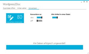
After specifying the XML file, the blog posts are displayed directly in a list. Now you can choose which blog post should be converted and whether it should be a Word or PDF document.
Now you can start exporting …
Depending on the number of posts and their length, the corresponding document is quickly available and can be edited as needed …
NES – Nintendo Entertainment System is certainly still a household name. It was the 8-bit game console from Nintendo, which was also sold in Europe in the mid-80s and had influenced the youth of the time. It is now a museum piece that already deserves the title “Retro”. Maybe for this reason, she begins to revive in the Retrogamergemeinde. For example, this year a remake of the NES in miniaturized form with modern technology and pre-installed games on the market.
Also via emulators for all kinds of platforms you can bring the old NES game titles back to life. In order to be able to serve these games “in the right way” (of course, it is also possible with the PC keyboard or via the touch screen on the mobile phone), the company 8Bitdo Tech has launched the NES30 GamePad Controller. It is a wireless bluetooth controller which was modeled on the original NES controller. It is equipped with an integrated rechargeable battery that can be charged via a MicroUSB cable connection. The controller is designed to be configured as a PC game controller, as a joystick, as a Bluetooth keyboard, and as a USB joystick. This can be realized via five different modes. These modes can be selected by keyboard shortcuts during power up. The table below shows the different modes:
Mode1
Mode2
Mode3
Mode4
Mode5
Joystick
BT-Keyboard
iCade
Emu-Touch
USB-Joystick
Power ON
START
START+B
START+A
START+X
Kabelverbindung
Blue LEDs are flashing
1x
2x
3x
4x
–
OS
WIN Android
WIN/Apple Android
Android Apple
Android Apple
WIN
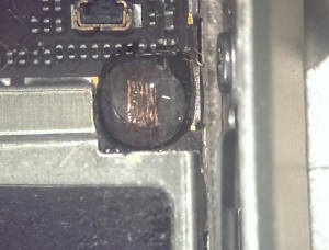
The picture shows the USB charging socket, to the right of which are two status LEDs.
The battery is located on the back of the board
die Platine des Controllers; der die Firmware des Mikrocontrollers kann aktualisiert werden
Contact mats represent the buttons. Under the two shoulder buttons are real micro buttons …
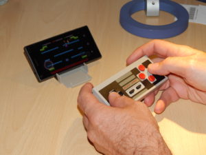
Here is the emulator “NES Emu” served on an Android phone with the NES30;)
Now it is already two years, in which I feed the “technology and retro blog” with contributions. Who would have thought that … By now some readers have strayed here and asked if I could introduce one or the other device here. Of course I will try to realize it if possible. Unfortunately, the rubric with the computers of the 80s is still empty. Here I still lack the “thread”, as I should process the whole – it floats me to every device before a small video in which the devices are to be shown in the living state. If someone has ideas for that … like.
I would like to say a big thank you to my colleague Mario Wehr, who provides me with the WordPress environment and thus offers excellent service!
In this sense: Merry Christmas and happy holidays!
This time, I’m not going to talk about a project or an “old equipment concept”, but would like to introduce some interesting users or their contributions from the YouTube portal. These are contributions from the field of computer, technology and science, which I personally like to look at.
First and foremost, I would like to mention the legend of modern computer history, which has fascinated me since my youth. The ComputerClub from WDR times with Wolfgang Rudolph and Wolfgang Back. The two moderators moderated the program Computerclub from the beginning of the 80’s to 2003 at Westdeutscher Rundfunk. In the topics, the two men are generally concerned with computers and peripherals, new developments in the field of electronics and present all sorts of things here. Many broadcast recordings are archived on YouTube, including by user janbras.
On 22 February 2003, the last broadcast was broadcast on WDR.
But the two protagonists have not given up the computer club and let him resurrect on July 24, 2007 on a German private broadcaster (NRW-TV).
However, the private broadcaster NRW-TV had to cease its operation in 2016 and so the program was Nr.186 recorded as the last in the studios of NRW.
But Wolfgang Rudolph has managed by fundraising to set up his own studio and now produces the CC2 from his private studio on his own.
In the background, a lot has changed, which confused the viewers and freaks a bit. Parallel to the broadcasts existed the page cczwei.de which was filled by both gentlemen. After 13.12.2016 suddenly a new page appeared. The new domain cc2.tv has been created. The now operates Rudolph alone. The domain cczwei.de continues to be operated by Mr. Back. He is assisted by Heinz Schmitz, who is now producing YouTube broadcasts with Mr. Back. Apparently, there were sufficient reasons for the gentlemen to part with years of community work. There never was an official explanation.
From the computer area, the guys from VirtualDimension report. They call their channel VD Hurrican and produce the formats: Virtual Worlds, Back in Time, Retroplay and On Site. The contributions are absolutely professional and mainly deal with home computers. With a lot of background information the old 8 and 16 Bit’er are presented here. Gameplay as well as fair reports and contributions from community events are also part of their repertoire. As an example here a link to the unboxing of an Amiga500 and its history. On the occasion of their 1000th subscriber on YouTube, they have published a 1000-subscriber special with a studio tour.
From the Australian continent, Dave Jones, also an inveterate technician, blogs. On his YouTube channel EEVblog, He also introduces electronic devices, explains their structure and operation. A special category in his channel are the so-called Mailbags. Here, Dave receives packages from people in the community who he opens in front of the camera and presents their content. This can be old computers and boards, or even new developments and prototypes of startups that are presented here.
A slightly different channel is that of an Englishman. He calls himself Photonicinduction and shows experiments with high performances. All sorts of appliances, such as vacuum cleaners, heating lamps, washing machines, loudspeakers, etc. are operated to the limit of their maximum performance data – and far beyond. The end of the device through destruction is the goal here.
A multi-band radio receiver from the year 1957 is the Tempocord of the company Minerva. The company Minerva was founded in Vienna in 1919 and began in 1924 with the production of radio receivers. The radios were initially made under the name Radiola or Aeriola. It was not until 1926 that the receivers were built under the name Minerva. The name Minerva was used until 1972.
The device here refuses any service after being supplied with the mains voltage. Thus, a first error is found quickly. The mains voltage does not reach the transformer. The reason for this is the mains fuses, which protect the transformer from all poles. Here are both broken. Probably because the transformer tap was clamped to 220V … Rectification and smoothing capacitors are fine.
The fuses, however, are wrapped in paper security wires, which are wrapped at the ends each with a brass clip. Due to the lack of availability of these old fuses, the fuse holders located on the Trafoprint have been swapped for current ones and reinserted. After carefully raising the supply voltage, the receiver was again able to elicit sounds …
It is a miniature quadrocopter, the size of the palm of your hand, which turns out to be a real powerhouse. It is controlled via a 2.4GHz handheld transmitter in six axes. The transmitter can be configured in Mode1 and Mode2 (throttle on the left lever). An LC display on the transmitter provides information about the current settings and a multi-color LED shows the switch-on status and also whether there is a radio connection to the drone.
The drone is built on a very light (crash-proof) chassis that also has “recursive predetermined breaking points”. This means that in the event of a crash, part of the affected engine boom unhooks instead of breaking off. You can then simply click it back in. There is also the option of installing the training frame supplied to protect the propellers.
The power supply in the transmitter is provided by four AAA batteries. The drone itself is powered by a LiPo battery that is charged using the USB adapter supplied. You only need a USB power adapter (mobile phone charging plug) or a PC / laptop as a voltage source.
When fully charged and with moderate flight, you can achieve a flight time of just under seven minutes. Before the end of the flight you will be warned by blinking LEDs, so that you can still land safely without any problems. Recharging the battery takes just under 30-45 minutes.
As a further special feature, the drone has a small camera on board. It offers a resolution of 480p. But there is also a version with a 720p camera. The camera data can be saved directly on a microSD card. The recording is started before the start of the flight by pressing a button on the drone and should be stopped again before switching off. The result is an “.avi” container file that can be played on any PC. The image section is not very wide-angled and is just acceptable for indoor use. You also need plenty of light to get reasonably sharp images. However, this works very well outdoors.
The controls can be learned quickly with a little practice and it is a lot of fun to use.
A good friend of the older generation of technicians is certainly the analog multimeter of the manufacturer Unigor. In this case, it is the model Unigor_6e from the 70s.
An excerpt from the preface of the operating manual:
The electronic instrument Unigor 6e combines the advantages of classical measuring technology with those of modern electronics.
It was specially developed for measurements in the field of electronics and for all those applications where practically no power is required. The high sensitivity is achieved by means of a battery-powered transistor amplifier.
The field effect transistor chopper for DC measurements and the multiple negative feedback guarantee high stability and negligible drift. The large measuring range and the high accuracy of 1% at AC and DC, allows universal use in the radio and television service in test field and laboratories.
The “6e” offers a total
54 DC and AC / voltage ranges
13 dB ranges
12 resistance and capacity ranges
2 temperature ranges
The electronic components of the meter are powered by four 1.5V batteries and take a current of about 2.5mA. The working range of the electronics is between 4V and 7V. The battery is switched on with the rotary switch (which also represents the R, C adjustment knob at the same time). To check the battery voltage, a check position is provided on the measuring range shutter.
The Unigor 6e also offers a variety of protective devices and is therefore protected against damage caused by incorrect handling and overload. (I can remember quite well from my school time that this is not always the case: D)
The Unigor 6e has an electromechanical circuit breaker function. Its relay responds to overloads with DC and AC and requires no auxiliary power. The protection therefore remains fully effective even when the battery switch or battery is switched off. The restarting in case of permanent overload is prevented by a special switching mechanism.
Furthermore, fuses provide protection at the higher current ranges to respond in the event of a short circuit or tripping of the circuit breaker.
Against overvoltages at the inputs are voltage arresters at the input terminals whose breakdown voltage is lower than that of the internal circuit.
A small mechanics project occupied me this time. It is again about a hot air engine. This time not about the Stirling engine, but the so-called “flame eater”.
During the search in the World Wide Web, I found, among other things, the website of Mr. James Maiwald. Mr. Maiwald is an ambitious modeler and specialist in the field of Stirling and vacuum engines. He develops and manufactures his own models in all variants and also offers them as a kit.
More precisely, it is a vacuum motor, which is popularly also called a flame eater. He is one of the hot air engines, but unlike the Stirling engine is an open system.
Technically speaking, it is an atmospheric engine, since here the external air pressure does the work (comparable to the first gasoline engine). As a result, the maximum piston force is limited to the product of piston area and air pressure. (Wikipedia)
And exactly one such model (lying the flame eater) is here. As I assemble the engine and the first time commissioning is seen in the following short video …
Now that the front panel is milled, it can be cleaned and the engravings are provided with black paint. After the varnish has dried in the indentations of the engraving, the supernatant paint is removed with solvent. Now the entire panel could be painted with clear lacquer.
While the paintwork on the front panel is drying, it’s time again for the wooden cabinet. The mounting holes for the boards, speakers, etc. were drilled and then the wood was embedded with a slightly darker wood stain. After drying, the wooden case also gets a clear coat.
In the next step, the operating elements (switches and rotary encoders) and the LC display are attached to the front panel. The milled webs for the speaker panel are covered with black fabric. (For the fabric had to serve a T-shirt).
The painting of the housing dried about a day. Now you can start mounting the speakers and the board.
Die Platine wird mit Abstandhaltern am Gehäuseboden verschraubt.
Now a suitable power supply is missing. For this purpose, a small power supply was built, which consists only of an iron core transformer with subsequent rectification, smoothing and voltage stabilization with a LM7809, ie 9V DC. For this, a small board was made (about 5x8cm) and also built into the housing with spacers.
Now that everything is assembled, the amplifier metrics and levels are again set and optimized with signal generator and oscilloscope.
The finished radio receiver now looks like this from the front …
und die Geräterückseite ist im nächsten Bild dargestellt:
In the short video, the radio can be seen in operation:
From the years 1970-1972 the radio receiver TEDDY AUTOMATIC 100 comes from the German manufacturer ITT – Schaub Lorenz. It is a multi-band receiver that covers the wave ranges of long wave, short wave, medium wave and ultrashortwave.
It is designed for mains and battery voltage (110-127V / 220-240V and for battery operation for 4×1.5 volt size AA cells).
The output power is 0.8 watts and is transmitted with a dynamic oval speaker.
The technical structure according to the manufacturer consists of 6AM circles and 9FM circles. The receiver principle is a SUPERHET with ZF 460kHz and 10.7MHz. The housing is made of plastic (thermoplastic) and has the dimensions of 215x127x70 mm with a weight of 1.2kg.