![]()
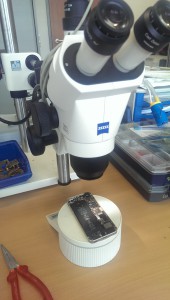
If the screen of an IPhone 5S gives up its ghost once (that is, it breaks or something similar), then the only thing that helps is swapping it. But beware ! The screws that hold the shield plate over the three Flexiprint connectors from the display are NOT the same length.
There are screws of different lengths here – even if you don’t necessarily recognize it optically. If you don’t take great care to screw all the screws back into the original threaded bushing during assembly, then it has already happened. The screws, which are approx. 0.1mm long, protrude over the socket and touch and damage the surface of the circuit board. If someone then takes it very carefully and tightens the screws firmly enough, then these are pressed into the second layer of the board. And that’s exactly where seven parallel conductor tracks run, which together require a width of almost 1000um (1mm). Now you can imagine what the tip of a screw can do here.
Exactly – chaos and destruction. The almost 50um wide conductor tracks have no chance against the colossus of screw with 1000um.
The result: Several of these conductor tracks are cut and the mobile phone cannot find all of its electronic components after switching on and starts the boot process again cyclically (with a brief flash of a blue screen)
Usually the device is now ready for the bin, or at least a new mainboard would be required. Just such a cell phone recently landed on my table.
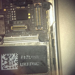
The connections to the display can be seen in Figure 1. At the bottom right, at the black spot, was the threaded socket into which the screw that was too long was screwed. If you now remove the socket, you can examine the damage.
The enlargement in Figure 2 shows clear impressions of the screw and a slight copper shimmer can also be seen.
However, the extent of the damage can only be determined if the layer is exposed in the area. With a suitable microscalpel I tried to expose the plane.
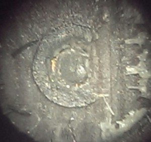
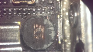
Figure 3 shows the conductor tracks and their interruptions. A repair with a soldering iron and repair wire is no longer possible here.

But since I have the opportunity to work on a wirebonder, I had the idea to use it for a repair attempt. The bonder from TPT-Wirebond offers the functions of wedge and ball bonding in different wire diameters. I could imagine wedgebonding as a suitable and feasible variant. The 25um diameter bond wire should fit. Only for the problem with the temperature of the chuck I had no solution. Because it is certainly not a good idea to heat up the iPhone. So I tried to bond cold. Without further ado, the chuck was disconnected from its power supply, the ultrasonic energy of the bonding tool increased and an attempt was started. Lo and behold, the bond holds. So, without further ado, six of the seven lines were made conductive again with gold wire bridges (Fig. 4) and then the display was connected for a start attempt. Lo and behold, the iPhone started normally again.
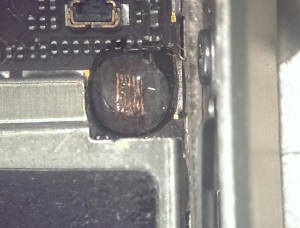
Now it was only a matter of protecting the sensitive bond wires from damage.
Here a synthetic resin two-component adhesive offered itself, from which I mixed an amount the size of a pin and covered the repair area with this droplet. After hardening, I was able to put the phone back together (at the repair site, of course, without a screw. A short function test was positive.;)