All posts by ingmarsretro

science kits PHILIPS EE 2000 series

Loading

EE2050
EE2050

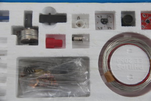
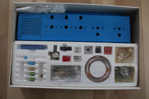
Another electronics kit from my youth is the Philips EE series. It dates approximately to the years 1976-1979. The box presented here is the EE2050. Unfortunately, this is no longer the original that I recorded back then, but a version bought on eBay. But this is a real collector’s item, because the box has never been recorded.

The boxes (EE2003 / 41/50/51/52) under my custody have unfortunately not survived the years. Since the modular system was designed in such a way that all components were “free”, ie not riveted to any sockets (just as they were also used in industry), I always used them. If I needed a resistor or capacitor quickly, the kit had to serve as a “donor”.

Befestigung des Bauteils auf der Grundplatte
Fixing the component on the base plate

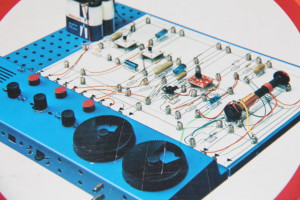
The concept of the modular system: It consists of a perforated plastic base plate through which a hairpin spring is inserted. This hairpin spring in turn holds a spiral spring. Now, between the hairpin spring and the upper end of the coil spring, the connection wire of the component can be clamped.

IMG_3779
Transistor on printed circuit board

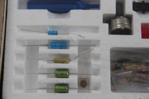
The components themselves are contained in the box as they are also commercially available. An exception here are only the transistors and transformers. They are mounted on a small printed circuit board, which facilitates assembly and also protects the component itself from mechanical stress.

In the final stage, the box consists of two bolted base plates, which in turn are bolted to a control panel. In this media console then turn capacitors, rotary potentiometers, buttons, bulbs and a speaker place. The number of experiments to build is also huge. The manuals are very well structured. They describe the basics of DC technology, as well as the operation of the circuits.

Here is an excerpt from the inscription of the electronics box. Note the gender-oriented spelling 🙂


Wonderful world of electronics – a mysterious world that every boy wants to get to know and understand. This electronic kit gives him the opportunity to easily gather his own insights in this field. The box contains a richly illustrated instruction book and over 150 items – e.g. 10 resistors, 5 capacitors, photocell and transistors. Thanks to the clamping system, the young electronics builder can assemble these parts completely independently and without prior knowledge to the following functional devices:

Burglar Alarm Systems, Amplifiers, Automatic Parking Lights, Humidity Indicators, Acoustic Relays, Morse Exercise Machines, Brightness Controls, Timers, Others – a total of 21 electronic devices and many interesting circuits.

With additional boxes the possibilities extend to the MW radio with loudspeaker. Proper engineers work with the same parts: all the boxes in the Philips Elektronik series are equipped with the most modern parts of today’s electronics in their original form.


IMG_3778IMG_3777IMG_3776IMG_3784


The steam engine

Loading

IMAG0062
Wilesco steamengine

The following piece is about 40 years old model steam engine from the manufacturer Wilesco. (Thanks to Manfred for the loan for the media preparation). The model consists of a highly polished and nickel-plated brass kettle, which is built into an old copper-colored boiler house with brick pattern. Heating is done with a dry spirit burner located under the boiler. The pressure vessel has a spring safety valve and a “Domdampfpfeife”. The pressure line is led to a single-acting pendulum cylinder, which in turn drives the crank and the flywheel on it via a connecting rod.Trockenspiritusbrenner.

IMAG0064The entire model is mounted on an iron plate. In order to be able to drive mechanical models with the machine, a pulley is mounted on the shaft of the flywheel. Since the model has been stored in a carton for the past forty years, a few small jobs have been done. Piston and crank were stiff and had to be cleaned and re-oiled. The crank was a bit out of alignment with the flywheel shaft.

IMAG0057The seals of the “Domdampfpfeife” and the pressure relief valve were also brittle and hardened and were replaced. Here I was able to use a suitable punching tool made of “new” old gasket material to knock out and insert two new gaskets. Now the model was a little bit freed from the dust of the last years and cleaned and a start attempt was nothing in the way.

Now the spirit burner could be filled with a small piece of dry spirit, which was probably even older than the machine itself. At least the original box looks like this:

IMAG0054 IMAG0055


Invalid Displayed Gallery


analogue multimeter – Unigor 3n

Loading

Unigor 3n
Unigor 3n

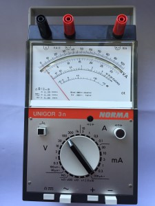
From the years from 1964 comes the analogue multimeter Unigor 3n from Norma, respectively Goerz-Metrawatt. It was characterized by the large measuring range of 52 measuring ranges, all of which can be selected with just one selector switch. The measuring mode and polarity reversal is realized with a push-button switch. All measurements (except the 10A range) are possible on just one terminal pair.

The measuring mechanism is a “clamping band measuring unit” with a very good vibration resistance and low self-consumption.

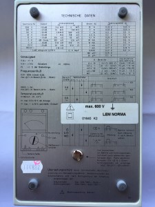
The internal resistance for voltage measurements is a maximum of 4MOhm in the highest measuring range (see photo technical data). The voltage drop in current measurements is given as 12mV in the 120uA range and 120mV in the 30A range. The measuring accuracy is 1% for DC and 1.5% for AC measuring ranges.

Like the Unigor 6e, the 3n model is also equipped with various safety features.

The power supply of the multimeter takes over a 1.5V mono cell.


Technische Daten
technical specification


analogue multimeter – Goerz Minitest

Loading

Goerz Minitest
Goerz Minitest

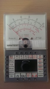
The Goerz multimeter, model: Minitest FE5101 dates from 1969 and was manufactured by the company Goerz Elektro Ges.m.b.H from Vienna.

Introductory sentence from the operating instructions: “It is a multi-measuring instrument, which is particularly suitable for service work in the field of news and radio technology and electronics due to its small dimensions and low weight as a pocket instrument It allows the measurement of: equal and AC voltages, DC and AC, resistance, capacitance and frequency. “

The internal resistance is 20kOhm for DC and 4kOhm for AC. The achieved accuracy is 2.5%

IMAG1503
inside view

As overload protection, the moving-coil meter is equipped with antiparallel-connected diodes.

In this model, the measuring ranges are not to be selected by a selector switch, but each individual measuring range is designed as a socket on the device. The sockets themselves are suitable for 2mm banana plugs. The power supply for the resistance measurement comes from a 3V dry cell battery (type 2R10 duplex battery).


IMAG1497
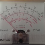
scale

For the measurement of the capacitance with this device an external voltage is necessary, because here no own alternating voltage generator is installed. This said external voltage is the 50 Hz mains voltage which is connected to the device via its own supply cable. So a capacity measurement up to 500nF can be achieved. Measurements greater than 0.5uF are no longer possible due to the low measuring frequency. Goerz supplied a polystyrene transport case for storage and transport.

Technology toys from the past – made of plastic

Loading

This article has nothing to do with electronics. In my retro-madness I was once again rummaging in the cellar of the parents’ house and discovered there behind dusty jars of musty-smelling cardboard boxes with unknown content. So what was left to me to uncover and view the contents of these cardboard boxes? And what came out here were other boxes of the well-known toy manufacturer “LEGO”. Some very dusty original boxes of Lego-Technik models and old washing powder boxes, which were filled with many, many colorful Lego bricks and other stuff and unfortunately also garbage. Actually, I thought to myself, these many plastic parts I can throw in the trash, because that will not play my son safe. Everything smells like cellar and is dirty and the work, everything to clean and sort will certainly no longer hurt anyone. But on the other hand is the really old toy from the 70s and 80s – so over forty years old. And that is exactly mine again. 🙂 Things from my childhood and memories of it.

So packed everything and transported home. And then, in painstaking work, sorted everything once into colors and freed it from rubbish and lego-foreign parts. And now the real work began. The goal should be to put together from the many parts of the old Lego-Technik models and missing parts as far as still available to order. The “vintage kits” should be restored as well as possible in their originality.

Well mixed and not complete Lego boxes

The photo shows a small part of the “excavated” Lego boxes. At least the boxes were already roughly cleaned. What came out after the painstaking sorting and construction work, however, can also be seen again.


Nr. 853 Lego Car-Chassis

The number 853 is the car chassis. The kit was sold in the year 1977. It consists of 601 parts and finished construction about 52cm long and 22cm wide.

The model has a four-cylinder in-line engine with two-speed gearbox and cardan shaft to the rigid rear axle. The gearbox as well as the pistons are functional. Likewise, the steering works. The seats are displaceable in the longitudinal axis.

In this series, the rear axle was still rigid and equipped with a differential. The following picture shows the tidy, restored kit.


Nr.: 8860 Car Chassis

Out of 671 individual parts, the car is to assemble chassis number 8860. The set dates from the year 1980 and has a size of 46×19 cm. Here was compared to the 853er already much expanded. The rear wheels are hung individually and have a suspension. The engine sits behind and this time is a four-cylinder boxer. Again, there is a transmission with three stages.

The seats are adjustable in the longitudinal direction and the inclination of the seat back can also be adjusted. Again, a rack and pinion steering is installed.

The original packaging is still available and looks like this in the sorted condition:


Nr. 854 Lego GoKart

From 1978 comes the Lego GoKart No. 854. It has the dimensions of approximately 21 x 13cm and is composed of 206 parts. On realized functions there is a rack and pinion steering and a single-cylinder engine, with a functional piston. The rear axle is rigid and the shaft is connected via a transmission with the crank of the piston. According to data in the network, this model has now reached cult status, as it should be one of the first Lego-technology models ever. Here is the original packaging and especially the number 9 on the front still available, then the model in collector’s circles should be really valuable. Unfortunately, I can not meet either criterion.

Nr. 856 Lego Bulldozer


With the model no. 856, Lego has launched one of the countless construction vehicle models on the market. The bulldozer dates back to 1979 and consists of 370 parts. The base is 24x 11cm at a height of 14cm. Of the functions of the blade is tiltable, raised and lowered. Two chains on gears represent the connection to the bearing surface.


Unfortunately, here too, only the box without internal division is available from the original packaging.


Nr. 8848 Lego Unimog

The Unimog 8848 from the year 1981 measures just under 30x12cm at a base of 14cm. It consists of 398 parts. As a functioning technology here again the steering, the tilting cargo area, as well as a raised and lowered, and tiltable bucket available.

Unfortunately, the box is missing the interior, otherwise the model is complete. Apart from the here presented, complete kits are still some more available, but where unfortunately too many parts missing. But some flea market or online raid of lego parts will probably arise once again to complete these sets and to be able to fully incorporate them into a retrospective collection.


An old tin …

Loading

… from the fund of grandmother’s cottage is this instant powder can.IMG_3873

The post does not have much to do with technology this time, but I’ve noticed this tin can because of the age and the designer graphics from times gone by. That’s why a few pictures of it must come in here. You do not see that very often anymore.

As can be seen in the photo, the instant powder can is the packaging of Ovomaltine.

Ovaltine contains the ingredients barley malt, milk powder, low-fat / de-oiled cocoa, whey powder, glucose syrup, yeast and honey. From the names of the ingredients is also the name Ovomaltine together: ovum (Latin egg) and malt (English malt). The high proportion of malt gives the Ovaltine their typical taste. Like the powder of instant cocoa drinks, Ovaltine is ready to drink after being stirred into cold or warm milk. (Wikipedia)

According to online research, the tin dates from the years 1954-1961 and was apparently used by my grandmother as a storage container for mothballs 🙂IMG_3880


IMG_3879 IMG_3878 IMG_3876

The storm glass – the weather forecast

Loading

Some time has passed since the last blog entry. On the one hand, I put this down to a lot of work, both professionally and privately, so that a bit of the energy for blogging was missing. The last days is the beautiful weather to blame. I preferred to spend my time riding a motorcycle instead of sitting behind the PC … But I also got a little gimmick again.

IMG_3952
FritzRoy storm glass

A colleague told me about it and at a large Internet mail-order company, I quickly found it. It is a so-called “FritzRoy storm glass“.

A storm glass is known for a long time from the seafaring. There it was used to predict weather changes. The storm glass is a glass cylinder filled with two liquids and hermetically sealed. The fluids are usually camphor and alcohol in saturated form, which do not mix but form small crystals. The formation of these crystals is related to the weather change. For a long time it was believed that the crystals react to changes in air pressure. Recent research allegedly suggests that the crystals react to electromagnetic fields called sferics. These sferics are preferably formed in low pressure areas. Thus, the storm glass shows the approach of a low pressure area and thus the bad weather.


IMG_3956
Crystals as weather forecast

The table (from the CarloMilano user manual) shows the different crystal weather relationships.

Clear liquid The weather is sunny and clear
Flaky liquid It is cloudy. Precipitation is possible
Small flakes It is foggy or damp
Little stars A thunderstorm is coming up
Little stars on a beautiful winter day It will snow
Big flakes It is covered. Snow is possible
Many crystals on the ground There is frost
Crystals on the surface It is getting stormy

IPhone 5s under the wirebonder

Loading

IMAG1839
IPhone 5S the maginfier glass 🙂

If the screen of an IPhone 5S gives up its ghost once (that is, it breaks or something similar), then the only thing that helps is swapping it. But beware ! The screws that hold the shield plate over the three Flexiprint connectors from the display are NOT the same length.

There are screws of different lengths here – even if you don’t necessarily recognize it optically. If you don’t take great care to screw all the screws back into the original threaded bushing during assembly, then it has already happened. The screws, which are approx. 0.1mm long, protrude over the socket and touch and damage the surface of the circuit board. If someone then takes it very carefully and tightens the screws firmly enough, then these are pressed into the second layer of the board. And that’s exactly where seven parallel conductor tracks run, which together require a width of almost 1000um (1mm). Now you can imagine what the tip of a screw can do here.

Exactly – chaos and destruction. The almost 50um wide conductor tracks have no chance against the colossus of screw with 1000um.

The result: Several of these conductor tracks are cut and the mobile phone cannot find all of its electronic components after switching on and starts the boot process again cyclically (with a brief flash of a blue screen)

Usually the device is now ready for the bin, or at least a new mainboard would be required. Just such a cell phone recently landed on my table.

IMAG1829_1
figure 1

The connections to the display can be seen in Figure 1. At the bottom right, at the black spot, was the threaded socket into which the screw that was too long was screwed. If you now remove the socket, you can examine the damage.


The enlargement in Figure 2 shows clear impressions of the screw and a slight copper shimmer can also be seen.

However, the extent of the damage can only be determined if the layer is exposed in the area. With a suitable microscalpel I tried to expose the plane.

IMAG1827_1
figure 2
IMAG1831
figure 3

Figure 3 shows the conductor tracks and their interruptions. A repair with a soldering iron and repair wire is no longer possible here.


figure 4

But since I have the opportunity to work on a wirebonder, I had the idea to use it for a repair attempt. The bonder from TPT-Wirebond offers the functions of wedge and ball bonding in different wire diameters. I could imagine wedgebonding as a suitable and feasible variant. The 25um diameter bond wire should fit. Only for the problem with the temperature of the chuck I had no solution. Because it is certainly not a good idea to heat up the iPhone. So I tried to bond cold. Without further ado, the chuck was disconnected from its power supply, the ultrasonic energy of the bonding tool increased and an attempt was started. Lo and behold, the bond holds. So, without further ado, six of the seven lines were made conductive again with gold wire bridges (Fig. 4) and then the display was connected for a start attempt. Lo and behold, the iPhone started normally again.


IMAG1837_1
figure 5

Now it was only a matter of protecting the sensitive bond wires from damage.

Here a synthetic resin two-component adhesive offered itself, from which I mixed an amount the size of a pin and covered the repair area with this droplet. After hardening, I was able to put the phone back together (at the repair site, of course, without a screw. A short function test was positive.;)


Beware of electrical goods from the far east

Loading

DSC_2196The other day I noticed with a cold-device connection cable that the cable sheath has come loose in the area of ​​the strain relief. The wires came out. By itself, this is nothing special, if not here, apart from the unusual colors, the unusually small diameter of the wires in the eye would sting.

DSC_2199
left: cable without CE marking right: standard cable
DSC_2198
Plug without any test marks.

Normally, such a jacket cable with 16A / 250V and a CE mark is marked on the plug. The cross section of the stranded wires is 1.5mm².  The cable here on the photo but an indication of 10A / 250V was printed and NO CE sign available. The strands have a cross section of less than 0.5mm² !! Who uses such a cable and for example operates a heater with it, then may not be surprised if a quick fire breaks out … Unfortunately, I can not understand with what device I got this cable included. But it does not conform to the valid standards and represents a danger in the enterprise. In any case: Keep away from such products!

Wickie, Slime and Paiper

Loading

_20160611_185029
ISBN 3-205-98989-9

It does not have anything directly to do with technology, but perhaps fits under the title “retro” as a post very well in the blog: A book for browsing memories of the 70s and 80s is the band “Wickie, Slime and Paiper” by Susanne Pauser and Wolfgang Ritschl. The book was published in 1999 by Böhler-Verlag Wien. It is a printed summary of an online forum as a souvenir album for the children of the seventies. It mentions numerous products and fashions, television and radio programs that were up to date at the time and is discussed and commented by the protagonists of the forum, themselves children of the seventies. The print is accompanied by scanned images of posters, catalogs, advertising slogans.


wsup2
Eskimo  ice-pricesheet(prices in Austrian Schilling 😉 )