34 total views
 I have another small contribution to make on the subject of “Aging and Homematic Smart Home”. Many thanks to Fritz for the preparation and analysis.
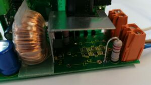
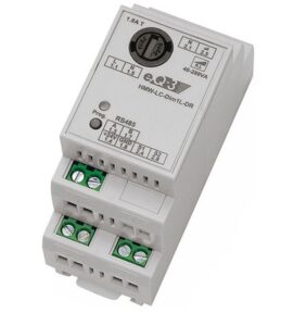
As in the last post “Homematic actuator quick repair”, this time it is again about a device from the Smart Home series. It is the dimmer actuator with the designation “HMW-LC-Dim1L-DR”. This is a phase control dimmer actuator for incandescent lamps and low-voltage halogen lamps with conventional transformers. Many modern LED lamps can also be controlled with this dimmer. The actuator belongs to the “wired” series, which means that it is not connected to the CCU via the BidCos radio protocol, but via the RS485 bus. The actuator receives the power supply for data communication from a 24V power supply unit. This also supplies the µC in the actuator. The network side is supplied with control data from the low-voltage side via an optocoupler. This ensures galvanic isolation. On the network side there is a dimmer controller module, which in turn controls the triac. This controller must be supplied with a voltage of approx. 15V. To generate this, the manufacturer has built in a capacitive voltage divider. And this is where the aging problems begin …
The error pattern manifests itself as follows: The connected light source cannot be dimmed or switched on. However, the dimmer is communicating correctly with the bus. The red function LED lights up correctly. The commands for “Off” and “On” via buttons are also displayed in the CCU.
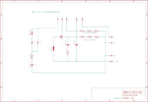
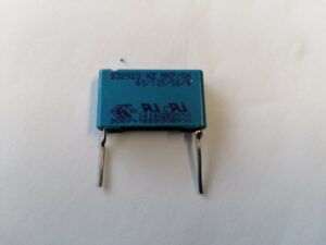
The cause: According to the data sheet, the IC U2008, a dimmer control module, is supplied with a voltage of DC 15V. In this case, the supply voltage was significantly lower (at approx. 5.8V). This supply voltage is made the 330nF / 275V X2 capacitor C4. The capacitor is optically in perfect condition, but a simple capacitance measurement quickly shows that nothing fits here. The capacitor C4 only had a capacity of approx. 30-40nF. So it’s like so often -> It was the capacitor: D
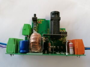
After the replacement, the voltage on the U2008 was ok again and the dimmer is doing its job again. As a preventive measure, the two other X2 capacitors on the board (C1 47nF / 275V and C2 100nF / 275) were replaced.
