NES Classic Mini : Off with exorbitant prices

Loading

The Nintendo company launched the Nintendo Classic Mini game console and put it on sale in 2016. It is a revival of the original 8-bit game console Nintendo Entertainment System from 1983 (release in Japan) and 1986 (release in Europe). The original NES console has sold around 61 million times and was replaced in 1992 by the SNES (Super Nintendo Entertainment System) a 16-bit console. The popularity of the Nintendo consoles is apparently so great that the new edition was sold out shortly after its release with a retail price of around 60 euros. Here traders sensed the big deal and offered the devices on Amazon, ebay and the like at sometimes horrendous prices. Even now, almost a year later, they are still not available for less than 100 euros. And Nintendo doesn’t produce any other units either. Instead, the same game began with the revival of the SNES series in miniature.

The NESPI in its packaging

But there are other ways you can get a miniaturized version of this console for a lot less money. For a few euros you get a case called NESPI CASE, which corresponds to the NES CLASSIC MINI, but with one big difference: you can install the computer yourself in the form of a Raspberry PI. This opens up countless possibilities to use emulator software to recreate your own consoles using software. The NESPI case has an integrated 4 port USB hub and a LAN Ethernet connector that leads the connections of the Raspberry PI to the outside. Two USB ports are arranged in such a way that they serve as controller connections. The other two USB ports and the Ethernet connection are located under the device flap, where the game modules were once inserted. The device is equipped with a power switch with a power LED and a reset button.

NESPI Case unpacked
Controls and connections

The housing is supplied with pre-assembled adapter boards. The screws for mounting the Raspberry Pi and the housing shells are also included in the scope of delivery. A small included Phillips screwdriver and a piece of paper with assembly instructions make things even easier.

Raspberry PI in NESPI-Case

The LAN and USB ports of the RaspberryPi are routed to the outside via the cables and plugs on the adapter boards. Once the plug connections have been made, the RapsberryPI board can be screwed into the housing. Optionally, a 5VDC fan with the dimensions 30x30x10mm can also be attached to the housing cover using locking lugs. A two-pole pin header is available on the circuit board for the power supply of the fan. Once everything has been installed and connected, the upper part of the housing can be screwed on.

Raspberry Pi eingebaut

The software can now be set up. I prefer the images from retropie or recalbox. More information can be found on the relevant websites. Once the desired emulators have been set up, you only have to transfer the game files, the so-called “Roms”, that is, binary copies of the game modules of the original hardware in a .bin or .rom or .iso file etc. to the SD card or USB Copy the stick and integrate it into the “EmulationStation”. And you’re ready to go. The USB controllers in the NES look are also available for just a few euros from China …
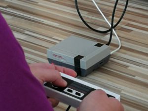
NESPIE with NES-Nachbau “ChinaController” attached


an old NES classic


VFD clock with date, day of the week and sound

Loading

I received a new kit for vacuum fluorescence display from Günter (gr-pojects). Thanks a lot!

It is a clock with Type IV-11 vacuum fluorescent display tubes for hours, minutes and seconds, and an IV-18 tube for date display, and IV-3 for displaying the day of the week. The clock consists of a mainboard with power supply, CPU, MP3 module and driver blocks for the tubes. The time is set and synchronized via an externally connected DCF-77 receiver. Later, the board will be extended with a real-time clock circuit. The power supply for the entire circuit comes from a small plug-in power supply with 12V / 1.2A. The total power consumption is about 450mA. As a special feature, the clock has a small MP3 sound module with MicroSD card slot. This receives from the microcontroller via the serial interface every quarter of an hour a corresponding command to play an MP3 file. Thus the quarter of an hour is signaled with a “gong beat”, half an hour with two and three quarters of an hour with three “gong strikes”. At the full hour, the corresponding time is announced.

The entire circuit is built into an aluminum-acrylic housing. All fittings are milled and screwed. A video of the structure and the function can be seen below:

Philips “Sonate” Philetta Euro280

Loading

Philips Philetta Euro 280 “Sonate”

In the years 1968 to 1970, the radio receiver was built with the inscription “Philetta Euro 280” by Philips. It is a small multi-band receiver with transistor equipment. The type designation 12RB280 / 30 with the inscription “Sonata” seems to be another version of this model. In any case, I have dug up the version “Sonata” – once again from the depths of the Kellergefilde – and after superficial cleaning connected to the mains. Immediately after switching on, the scale illumination lights up and a loud 50 Hz hum can be heard from the loudspeaker. Increasing the volume level adds some noise. So switched to the FM band and searched for a station – and lo and behold, it works. Only the buzzing disturbs. Otherwise, the device works without any major problems. To find the cause of the humming, you begin with the troubleshooting as usual in the power supply.

entfernte Rückwand

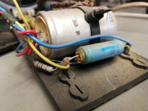
The rear panel is quickly removed and the power supply unit, consisting of a, mounted on a support plate transformer including rectifier and filter capacitors removed. Now, without using the oscilloscope and the multimeter, you can immediately see where the ravages of time have left their mark. The two electrolytic capacitors do not look quite healthy anymore.

A quick measurement of the voltages brings certainty. The DC voltages have a decent ripple, which causes the “hum”. So the function of the electrolytic capacitors to smooth the DC voltage is no longer, or poorly, given. A measurement of the capacities confirmed that. So I renewed the capacitors.

Power supply with renewed capacitors

Immediately after switching on, even before I had the probe at the measuring points, a noise was heard without “humming”. The oscilloscope image now showed a clean DC voltage – almost no ripple. The receiver worked again very clean, without disturbing background noise. That was apparently the only mistake.

Technical information:

The main principle of the receiver is a superhet (according to the superposition principle) with an IF of 460/10700 kHz. The waveband of the receiver:

frequency scale
  • long wave
  • medium wave 1 (520-1400kHz)
  • medium wave 2 (1400-1600kHz)
  • shortwave
  • UKW

The output stage has a power of 3W, which is converted into sound energy in a dynamic loudspeaker with permanent magnetic excitation. The case is made of plastic and has the dimensions 43×17.5×10.5cm with a weight of 2.4kg. The receiver is supplied with 220V / 50Hz mains voltage.


Walkman City Bummler from the 80s

Loading

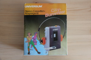
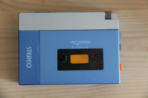
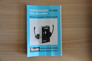
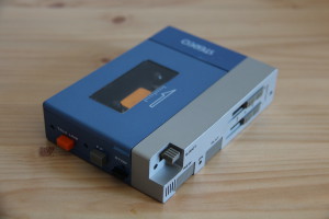
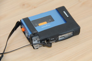
IMG_3810From the early 1980s comes the “City Bummler” a mobile, portable cassette player – in short a Walkman. At that time, I received it as a Christmas present during my middle school years. The special feature of this device was a built-in microphone and two headphone ports. So you could listen to music in pairs and if you wanted to say something without having to remove the headphones (or to reduce the volume), so you had to press only  an orange colored button and the intercom was active. The device was sold as a low-priced “replica” version of the first Walkman from Sony, the TPS-L2 which came on July 1, 1979 on the market. The citybummler was distributed by UNIVERSUM via the source mailer.

IMG_3812
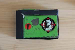
City Bummler with a self made coverplate after the original got broken

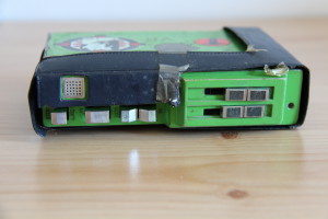
The device was delivered in a box with headphones, cassette pocket and carrying case with strap. For operation, three AA size 1.5V batteries were needed. The volume control is carried out with two separate sliders, so that each channel can be controlled separately. Unfortunately, the city loafer has not passed the last 35 years quite unscathed. Over time, the cassette cover was broken off, which I then replaced in my youth with a homemade tinplate lid. At some point I did not like the case color and I painted the device green. (or I just had green paint at hand). At least the “loafer” still exists and it works too.

IMG_3814I was then on the Web in search of a well-preserved, in the original state city loafer. However, the offer is extremely low and the few offers on online auction houses are not interesting because of the immense shipping costs.

IMG_3807
Fellow FE-1

But a compromise and at the same time a new piece in the collection is the FELLOW FE-1 Walkman. I got the most cheap and fully functional on a second-hand stock market.

IMG_3815
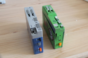
left: Fellow FE-1, right: City-Bummler
IMG_3817
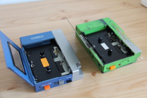
both devices in comparison

The Fellow is also a clone of the Sony TPS-L2. It differs essentially in the arrangement of the keys of the drive.


IMG_3811IMG_3809IMG_3808IMG_3821 IMG_3812 IMG_3814 IMG_3819


science kits PHILIPS EE 2000 series

Loading

EE2050
EE2050

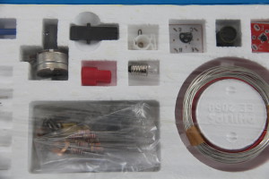
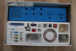
Another electronics kit from my youth is the Philips EE series. It dates approximately to the years 1976-1979. The box presented here is the EE2050. Unfortunately, this is no longer the original that I recorded back then, but a version bought on eBay. But this is a real collector’s item, because the box has never been recorded.

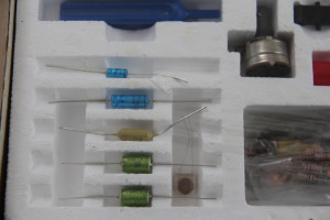
The boxes (EE2003 / 41/50/51/52) under my custody have unfortunately not survived the years. Since the modular system was designed in such a way that all components were “free”, ie not riveted to any sockets (just as they were also used in industry), I always used them. If I needed a resistor or capacitor quickly, the kit had to serve as a “donor”.

Befestigung des Bauteils auf der Grundplatte
Fixing the component on the base plate

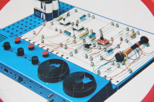
The concept of the modular system: It consists of a perforated plastic base plate through which a hairpin spring is inserted. This hairpin spring in turn holds a spiral spring. Now, between the hairpin spring and the upper end of the coil spring, the connection wire of the component can be clamped.

IMG_3779
Transistor on printed circuit board

The components themselves are contained in the box as they are also commercially available. An exception here are only the transistors and transformers. They are mounted on a small printed circuit board, which facilitates assembly and also protects the component itself from mechanical stress.

In the final stage, the box consists of two bolted base plates, which in turn are bolted to a control panel. In this media console then turn capacitors, rotary potentiometers, buttons, bulbs and a speaker place. The number of experiments to build is also huge. The manuals are very well structured. They describe the basics of DC technology, as well as the operation of the circuits.

Here is an excerpt from the inscription of the electronics box. Note the gender-oriented spelling 🙂


Wonderful world of electronics – a mysterious world that every boy wants to get to know and understand. This electronic kit gives him the opportunity to easily gather his own insights in this field. The box contains a richly illustrated instruction book and over 150 items – e.g. 10 resistors, 5 capacitors, photocell and transistors. Thanks to the clamping system, the young electronics builder can assemble these parts completely independently and without prior knowledge to the following functional devices:

Burglar Alarm Systems, Amplifiers, Automatic Parking Lights, Humidity Indicators, Acoustic Relays, Morse Exercise Machines, Brightness Controls, Timers, Others – a total of 21 electronic devices and many interesting circuits.

With additional boxes the possibilities extend to the MW radio with loudspeaker. Proper engineers work with the same parts: all the boxes in the Philips Elektronik series are equipped with the most modern parts of today’s electronics in their original form.


IMG_3778IMG_3777IMG_3776IMG_3784


The steam engine

Loading

IMAG0062
Wilesco steamengine

The following piece is about 40 years old model steam engine from the manufacturer Wilesco. (Thanks to Manfred for the loan for the media preparation). The model consists of a highly polished and nickel-plated brass kettle, which is built into an old copper-colored boiler house with brick pattern. Heating is done with a dry spirit burner located under the boiler. The pressure vessel has a spring safety valve and a “Domdampfpfeife”. The pressure line is led to a single-acting pendulum cylinder, which in turn drives the crank and the flywheel on it via a connecting rod.Trockenspiritusbrenner.

IMAG0064The entire model is mounted on an iron plate. In order to be able to drive mechanical models with the machine, a pulley is mounted on the shaft of the flywheel. Since the model has been stored in a carton for the past forty years, a few small jobs have been done. Piston and crank were stiff and had to be cleaned and re-oiled. The crank was a bit out of alignment with the flywheel shaft.

IMAG0057The seals of the “Domdampfpfeife” and the pressure relief valve were also brittle and hardened and were replaced. Here I was able to use a suitable punching tool made of “new” old gasket material to knock out and insert two new gaskets. Now the model was a little bit freed from the dust of the last years and cleaned and a start attempt was nothing in the way.

Now the spirit burner could be filled with a small piece of dry spirit, which was probably even older than the machine itself. At least the original box looks like this:

IMAG0054 IMAG0055


Invalid Displayed Gallery


analogue multimeter – Unigor 3n

Loading

Unigor 3n
Unigor 3n

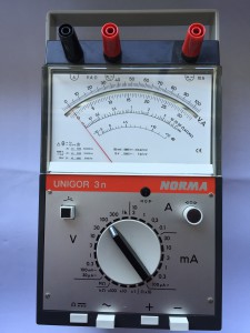
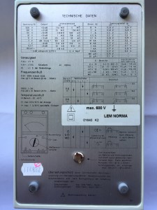
From the years from 1964 comes the analogue multimeter Unigor 3n from Norma, respectively Goerz-Metrawatt. It was characterized by the large measuring range of 52 measuring ranges, all of which can be selected with just one selector switch. The measuring mode and polarity reversal is realized with a push-button switch. All measurements (except the 10A range) are possible on just one terminal pair.

The measuring mechanism is a “clamping band measuring unit” with a very good vibration resistance and low self-consumption.

The internal resistance for voltage measurements is a maximum of 4MOhm in the highest measuring range (see photo technical data). The voltage drop in current measurements is given as 12mV in the 120uA range and 120mV in the 30A range. The measuring accuracy is 1% for DC and 1.5% for AC measuring ranges.

Like the Unigor 6e, the 3n model is also equipped with various safety features.

The power supply of the multimeter takes over a 1.5V mono cell.


Technische Daten
technical specification


analogue multimeter – Goerz Minitest

Loading

Goerz Minitest
Goerz Minitest

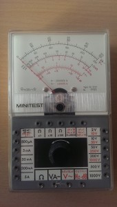
The Goerz multimeter, model: Minitest FE5101 dates from 1969 and was manufactured by the company Goerz Elektro Ges.m.b.H from Vienna.

Introductory sentence from the operating instructions: “It is a multi-measuring instrument, which is particularly suitable for service work in the field of news and radio technology and electronics due to its small dimensions and low weight as a pocket instrument It allows the measurement of: equal and AC voltages, DC and AC, resistance, capacitance and frequency. “

The internal resistance is 20kOhm for DC and 4kOhm for AC. The achieved accuracy is 2.5%

IMAG1503
inside view

As overload protection, the moving-coil meter is equipped with antiparallel-connected diodes.

In this model, the measuring ranges are not to be selected by a selector switch, but each individual measuring range is designed as a socket on the device. The sockets themselves are suitable for 2mm banana plugs. The power supply for the resistance measurement comes from a 3V dry cell battery (type 2R10 duplex battery).


IMAG1497
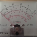
scale

For the measurement of the capacitance with this device an external voltage is necessary, because here no own alternating voltage generator is installed. This said external voltage is the 50 Hz mains voltage which is connected to the device via its own supply cable. So a capacity measurement up to 500nF can be achieved. Measurements greater than 0.5uF are no longer possible due to the low measuring frequency. Goerz supplied a polystyrene transport case for storage and transport.

Technology toys from the past – made of plastic

Loading

This article has nothing to do with electronics. In my retro-madness I was once again rummaging in the cellar of the parents’ house and discovered there behind dusty jars of musty-smelling cardboard boxes with unknown content. So what was left to me to uncover and view the contents of these cardboard boxes? And what came out here were other boxes of the well-known toy manufacturer “LEGO”. Some very dusty original boxes of Lego-Technik models and old washing powder boxes, which were filled with many, many colorful Lego bricks and other stuff and unfortunately also garbage. Actually, I thought to myself, these many plastic parts I can throw in the trash, because that will not play my son safe. Everything smells like cellar and is dirty and the work, everything to clean and sort will certainly no longer hurt anyone. But on the other hand is the really old toy from the 70s and 80s – so over forty years old. And that is exactly mine again. 🙂 Things from my childhood and memories of it.

So packed everything and transported home. And then, in painstaking work, sorted everything once into colors and freed it from rubbish and lego-foreign parts. And now the real work began. The goal should be to put together from the many parts of the old Lego-Technik models and missing parts as far as still available to order. The “vintage kits” should be restored as well as possible in their originality.

Well mixed and not complete Lego boxes

The photo shows a small part of the “excavated” Lego boxes. At least the boxes were already roughly cleaned. What came out after the painstaking sorting and construction work, however, can also be seen again.


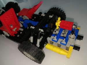
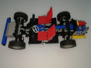
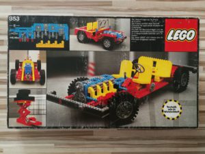
Nr. 853 Lego Car-Chassis

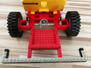
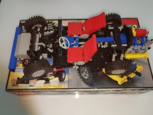
The number 853 is the car chassis. The kit was sold in the year 1977. It consists of 601 parts and finished construction about 52cm long and 22cm wide.

The model has a four-cylinder in-line engine with two-speed gearbox and cardan shaft to the rigid rear axle. The gearbox as well as the pistons are functional. Likewise, the steering works. The seats are displaceable in the longitudinal axis.

In this series, the rear axle was still rigid and equipped with a differential. The following picture shows the tidy, restored kit.


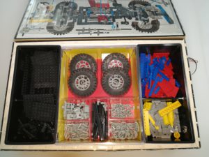
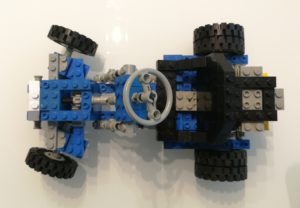
Nr.: 8860 Car Chassis

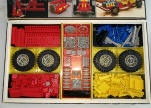
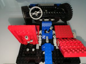
Out of 671 individual parts, the car is to assemble chassis number 8860. The set dates from the year 1980 and has a size of 46×19 cm. Here was compared to the 853er already much expanded. The rear wheels are hung individually and have a suspension. The engine sits behind and this time is a four-cylinder boxer. Again, there is a transmission with three stages.

The seats are adjustable in the longitudinal direction and the inclination of the seat back can also be adjusted. Again, a rack and pinion steering is installed.

The original packaging is still available and looks like this in the sorted condition:


Nr. 854 Lego GoKart

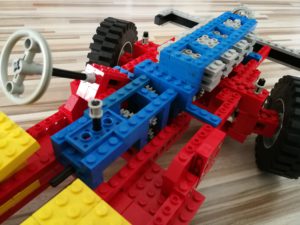
From 1978 comes the Lego GoKart No. 854. It has the dimensions of approximately 21 x 13cm and is composed of 206 parts. On realized functions there is a rack and pinion steering and a single-cylinder engine, with a functional piston. The rear axle is rigid and the shaft is connected via a transmission with the crank of the piston. According to data in the network, this model has now reached cult status, as it should be one of the first Lego-technology models ever. Here is the original packaging and especially the number 9 on the front still available, then the model in collector’s circles should be really valuable. Unfortunately, I can not meet either criterion.

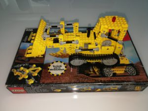
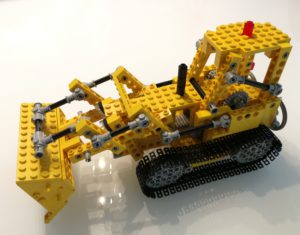
Nr. 856 Lego Bulldozer


With the model no. 856, Lego has launched one of the countless construction vehicle models on the market. The bulldozer dates back to 1979 and consists of 370 parts. The base is 24x 11cm at a height of 14cm. Of the functions of the blade is tiltable, raised and lowered. Two chains on gears represent the connection to the bearing surface.


Unfortunately, here too, only the box without internal division is available from the original packaging.


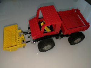
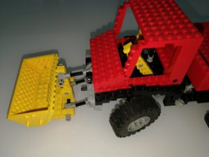
Nr. 8848 Lego Unimog

The Unimog 8848 from the year 1981 measures just under 30x12cm at a base of 14cm. It consists of 398 parts. As a functioning technology here again the steering, the tilting cargo area, as well as a raised and lowered, and tiltable bucket available.

Unfortunately, the box is missing the interior, otherwise the model is complete. Apart from the here presented, complete kits are still some more available, but where unfortunately too many parts missing. But some flea market or online raid of lego parts will probably arise once again to complete these sets and to be able to fully incorporate them into a retrospective collection.


An old tin …
Loading

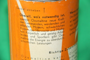
… from the fund of grandmother’s cottage is this instant powder can.IMG_3873

The post does not have much to do with technology this time, but I’ve noticed this tin can because of the age and the designer graphics from times gone by. That’s why a few pictures of it must come in here. You do not see that very often anymore.

As can be seen in the photo, the instant powder can is the packaging of Ovomaltine.

Ovaltine contains the ingredients barley malt, milk powder, low-fat / de-oiled cocoa, whey powder, glucose syrup, yeast and honey. From the names of the ingredients is also the name Ovomaltine together: ovum (Latin egg) and malt (English malt). The high proportion of malt gives the Ovaltine their typical taste. Like the powder of instant cocoa drinks, Ovaltine is ready to drink after being stirred into cold or warm milk. (Wikipedia)

According to online research, the tin dates from the years 1954-1961 and was apparently used by my grandmother as a storage container for mothballs 🙂IMG_3880


IMG_3879 IMG_3878 IMG_3876