Thx MrSputnik for evolving it (1 day eh. 🙂 ).
Carry On My Wayward Son(s) 🙂
[local /files/2010/11/Film_3.flv]
Thx MrSputnik for evolving it (1 day eh. 🙂 ).
Carry On My Wayward Son(s) 🙂
[local /files/2010/11/Film_3.flv]
I never thought that could be a problem. Well after digging around for HTTP+SSL (multiple certificates) and after understanding how it works, yes this is definitely a problem :-).
But there is light at the end of the tunnel called SNI (Server Name Indication). SNI is an extension for TLS .
The idea behind SNI is that the clients domain name request is deferred until the certificate is exchanged between the the two parties . This gives the server the change to switch to the right named virtual host :-)…. yeah thats cooooool.
See here RFC3546 (Section 3.1) for an in deep description.
SNI works with (according wikipedia):
If you want to use SNI for your server you have to put your *.443 hosts configs into one file.
Listen 443

NameVirtualHost *:443

# Also accept connections from none SNI capable hosts
SSLStrictSNIVHostCheck off

# This is our default virtual host.
 DocumentRoot /www/blub1
 ServerName www.blub1.at

# Other directives here

DocumentRoot /www/blub1
 ServerName www.blub.at

# Other directives here
have fun
Mario
16 for me the rest for the students 🙂
")
A few posts before I wrote about about the project “Campus Door System “. In our real time environment part of the project we are using the miniMODUL-167 which is equipt with an RTC-8583.
For I²C < -> RTC interfacing we are using sources which can be downloaded from the Phytec ftp servers. For the whole project we have been using this source without problems 🙂
After rolling out the system to one of our customers a few weeks later the system suddenly stopped, only a reset could clear the situation. Our in-house systems have never shown this kind of symptoms. So what the hell was going on?
After some days I found out that the problem might be located on the RTC part. After the crash the RTC delivers such funny things like 56 h 78 m 99 s , lol, ok so the RTC counters only compare for equals thats for sure :-). But what part of our code is setting the RTC ?
To make it short, the problem was a combination of our system architecture and the way the used I²C library is working.
Because the I²C library has a low level layer which is responsible for generating the bit pattern of the I²C data, this part of the code is prone to wrong designed interrupt architecture.
Sample of the low level I²C:
/****************************************************************************/
/* sends one bit to I2C-bus, also used for sending ACKNOWLEDGE condition    */

void I2CSendBit(BYTE State) {
// I2CDelay();
   I2CPutSCL(0);                       /* setup SCL (redundant)             */
// I2CDelay();
   I2CPutSDA(State);                   /* setup SDA                         */
// I2CDelay();
   I2CPutSCL(1);                       /* enable SDA writing                */

// I2CDelay();                         /* let SCL get stabilized High       */

   while(!I2CGetSCL());                /* wait until SCL-line is released   */

// I2CDelay();
   I2CPutSCL(0);                       /* disable SDA writing (SDA is now   */
                                       /* clocked)                          */
// I2CDelay();
   I2CPutSDA(1);                       /* release SDA */
}

/****************************************************************************/
/* set SCL-line to desired state                                            */

void I2CPutSCL(BYTE State)
{
 if(!State)
 {
 I2C_PORT &= ~I2C_SCL_MSK;             /* set SCL-Line to ZERO                */
#ifdef __C166__
 I2C_PORT_DIR |= I2C_SCL_MSK;     /* set SCL-Pin for OUTPUT Mode        */
#endif
 /* enable output AFTER setting of    */
 /* correct level to avoid '1'-level  */
 /* spikes                            */
 }
 else
 {
#ifdef __C166__
 I2C_PORT_DIR &= ~I2C_SCL_MSK;    /* set SCL-Pin for INPUT Mode        */
#endif
 /* this is possible because of the   */
 /* external pull-up resistor !       */
 /* set SCL-line to ONE               */
 I2C_PORT |= I2C_SCL_MSK;
 }
}

/****************************************************************************/
/* read state of  SCL-line                                                  */
/* WARNING: This function should be used only if SCL-line is in High-level !*/
/* (This function is for used only for realizing the Slow-Down-Mode)        */

BYTE I2CGetSCL(void)
{
 #ifdef __C166__
 I2C_PORT_DIR &= ~I2C_SCL_MSK;            /* set SCL-Pin for INPUT Mode        */
 #endif

 if(I2C_PORT&I2C_SCL_MSK)
 return(1);                               /* read SCL-line status              */
 else
 return(0);
}
This is exactly what happend. In-house we have only a certain amount of readers connected to the external buses of the access system. But our customer has over 100 readers installed. So the interrupt load was at a level where the situation could arise that at the moment where the I²C bit pattern is generated a few interrupts suspended the pattern generation. This leads in the worst case to a write instead of a read flag 🙂
A quick fix was to globally disable interrupts in I²C write situations or a better solution would be to move the accourding code to a high priojority interrupt.
I’m also writing this because some of my colleagues also use this lib – and yes they also do not read manuals 🙂
have fun
Mario
This time he is building our heavy current switch.
[local /files/2010/10/0001.flv]
thx Markus
 One week ago the Android part of the mobile application has started. Two students and Markus, the Android-Application project leader, are going to develop the Android version of the current iPhone app. prototype.
Fortunately he has managed to get the cell phone carrier Orange on board. Orange has sponsored two state of the art smart phones (Samsung Galaxy Leo) running Android OS version 2.2 for the development of the app. The project has officially started and now we are all looking forward to get all the parts of the project, the middle ware (which is my part), the iPhone app and the Android-app. up and running.
have fun
Markus & Mario
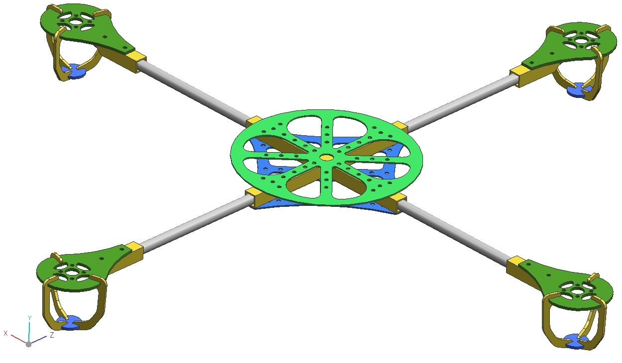
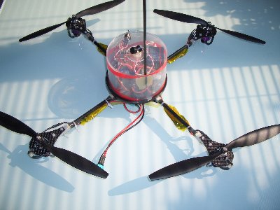
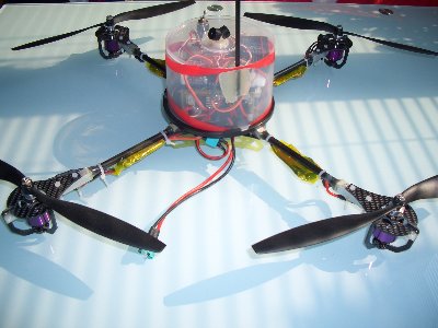
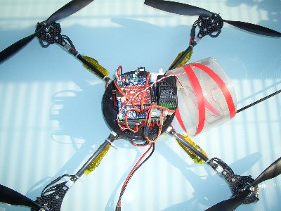
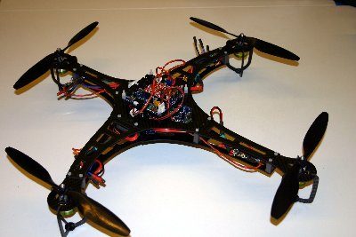
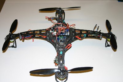
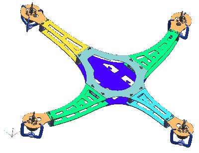
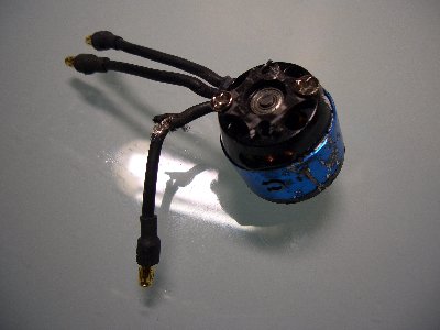
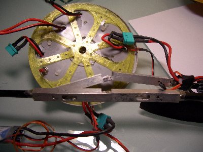
As some of you properly know one of my hobbies is to play around with drone technology 🙂 . Particular Quadrocopters are the name of the game. Currently I’m building 7 Quadros with colleagues and students.
Here are some impressions of my predecessor Copters 🙂
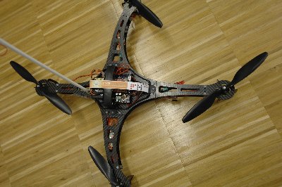
At a test flight with one of our early prototypes we had lets say a unforeseen occurrence.
The short story … After hovering around at our testing side and testing some controller configs our Copter suddenly defies our control. The QuadroCopter was just landed by our brave pilot, as it suddenly spinup its motors and started for a moderate and well balanced ascent towards the sky. You could imagine, in my brain was only one sentence, WHAT THE HELL was going on. Yeah and the hell was really going on. After a minute or so the Copter was only a tiny black point in the sky… nice… there it goes… up to the stars… This would be a new altitude record for Quadrocopters… indeed. I did a short phone call to notify our police… just in case…. :-).
The End of the Story…, nothing stays in the sky, this is also the case with our Copter.
A picture is worth a thousand words, see for your self what we found after the “landing”
One thing I should mention: The failure was a configuration mistake on our side!
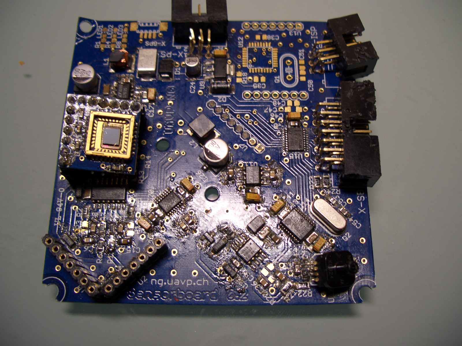
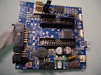
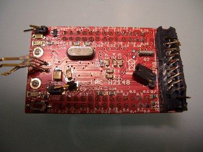
We wanted to used the -IE and the -USB versions with one Daughterboard. The operation purpose should involve longterm logging of various data sources with Ethernet, RS232 or USB interfaces like GPS localization data, ambience data, energ![]() y consumption data, operational data from small water power plants ….
y consumption data, operational data from small water power plants ….
Since the used DimmPcs are also equip with a 44-pin mini-IDE interface we have plenty of space for log data. (For example we use the Flash Modules from Transcend).
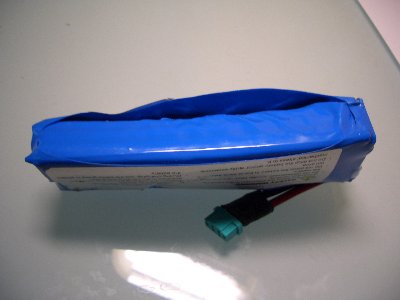
The Daughterboard should also be selectively powered with 24V or 5V.
For data transfer we use a USB Samba75 Quad Band GSM/GPRS/EDGE  modem from Falcom.
We have also a special version with external i²C and SPI interface connectors.
Daughterboard Top up

Daughterboard bottom up


A new Project raised behind the horizon. Since two months the student Daniel L. and  myself are working on an iPhone App for our students.
The Name is secret (for now) so I call it” The APP.” 🙂
Currently we have more or less finished with the application design and now we have started with the implementation of the first prototype. As the mobile part heavily depends on remote data we also needed a Backend for the core data distribution. Daniel is currently working on the implementation of the iPhone part, and I’m working on the server Backend.
We needed some kind of webservice infrastructure to get the data to/from the mobile application. I have chosen Tomcat for our Server infrastructure, maybe with Apache as first responder. The used framework for the stuff behind is Restlet. The Backend is designed to response with XML or JSON plain/gzipped data formats, depending on the received Accept Headers.
Representational State Transfer ( Rest ) is build around around the transfer of “representations” of “resources”. A resource is mostly an URI endpoint if we use HTTP. Compared to SOAP RPC every developer has to design and implement his own set of functions which represent the interaction interface between the web. App. and the backend. Rest uses the existing HTTP “methods” GET, POST, PUT, DELETE as the command interface. Really cool 🙂 Rest responses are not limited to HTML one can use XML, JSON, binary…
more to come…
have fun
CUAS SCALA MedIT Dream Team:
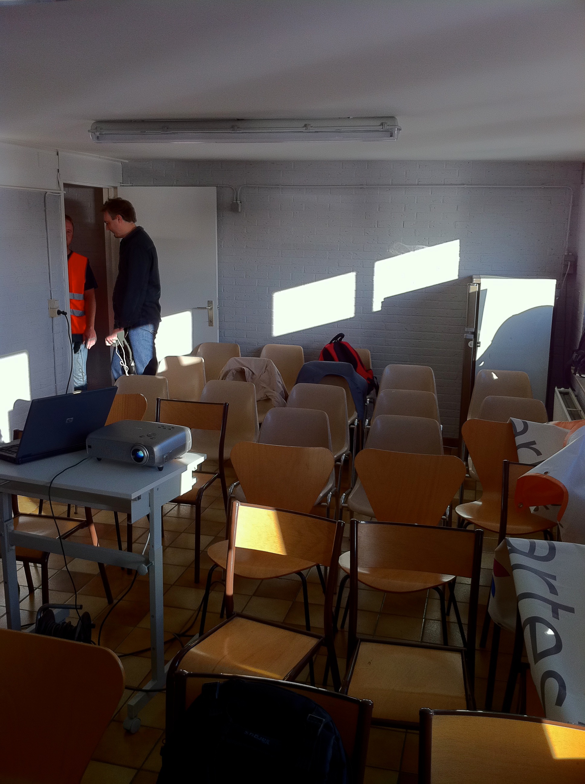
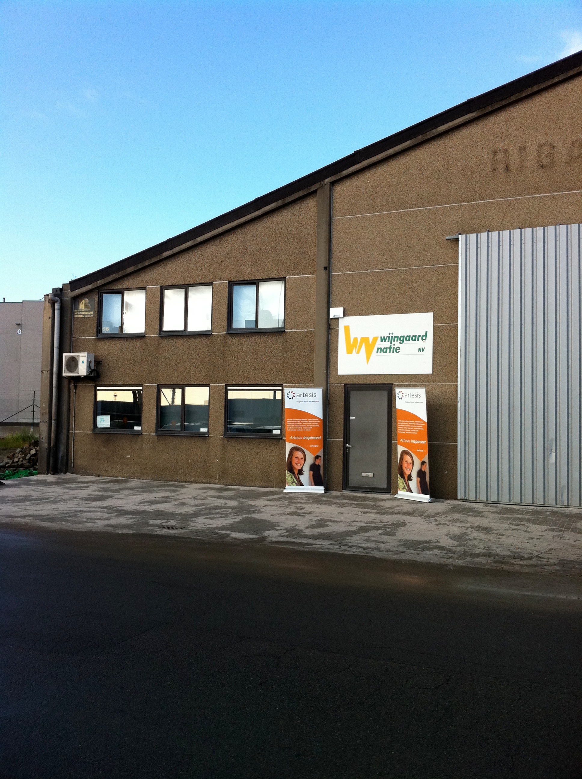
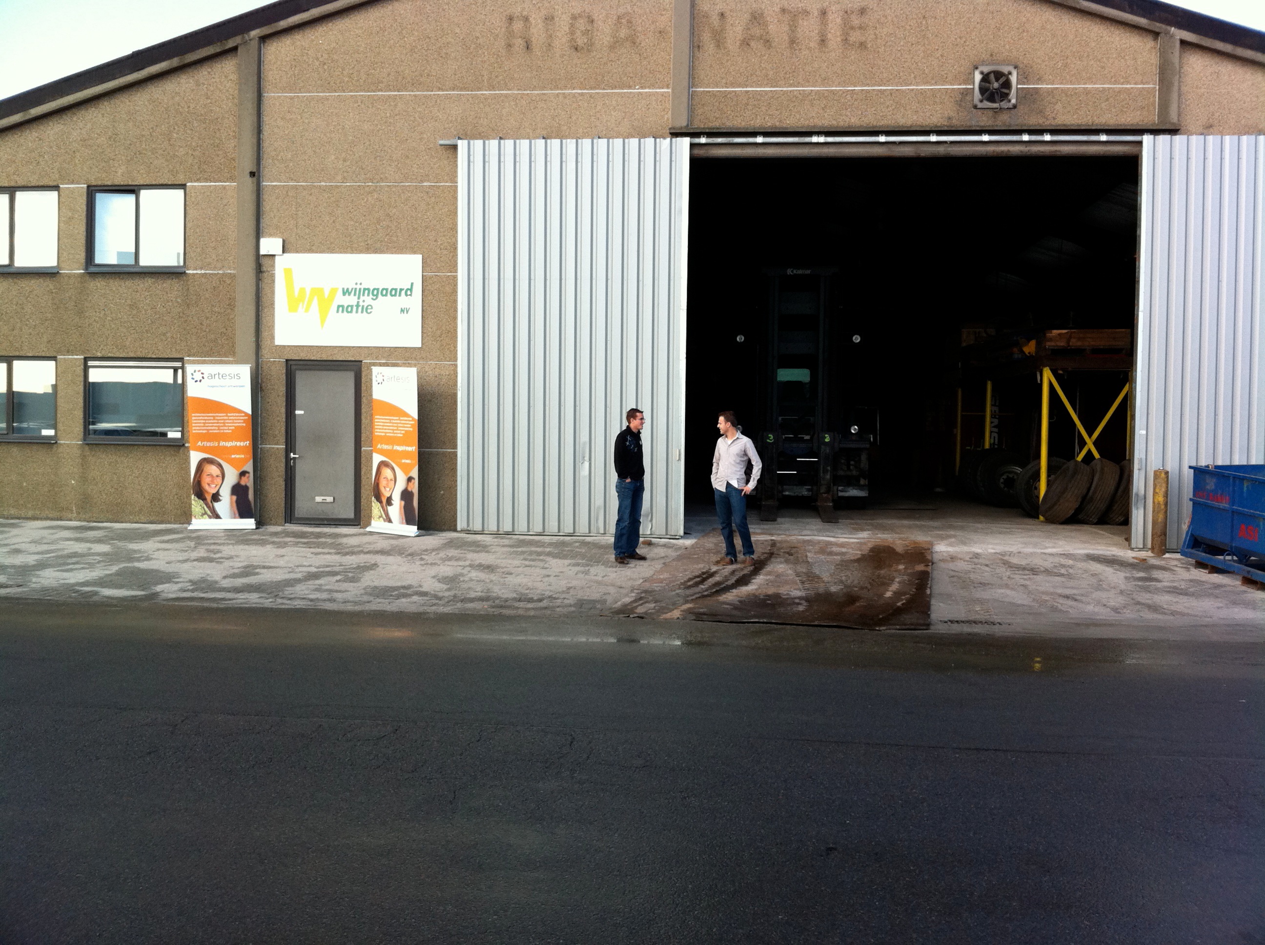
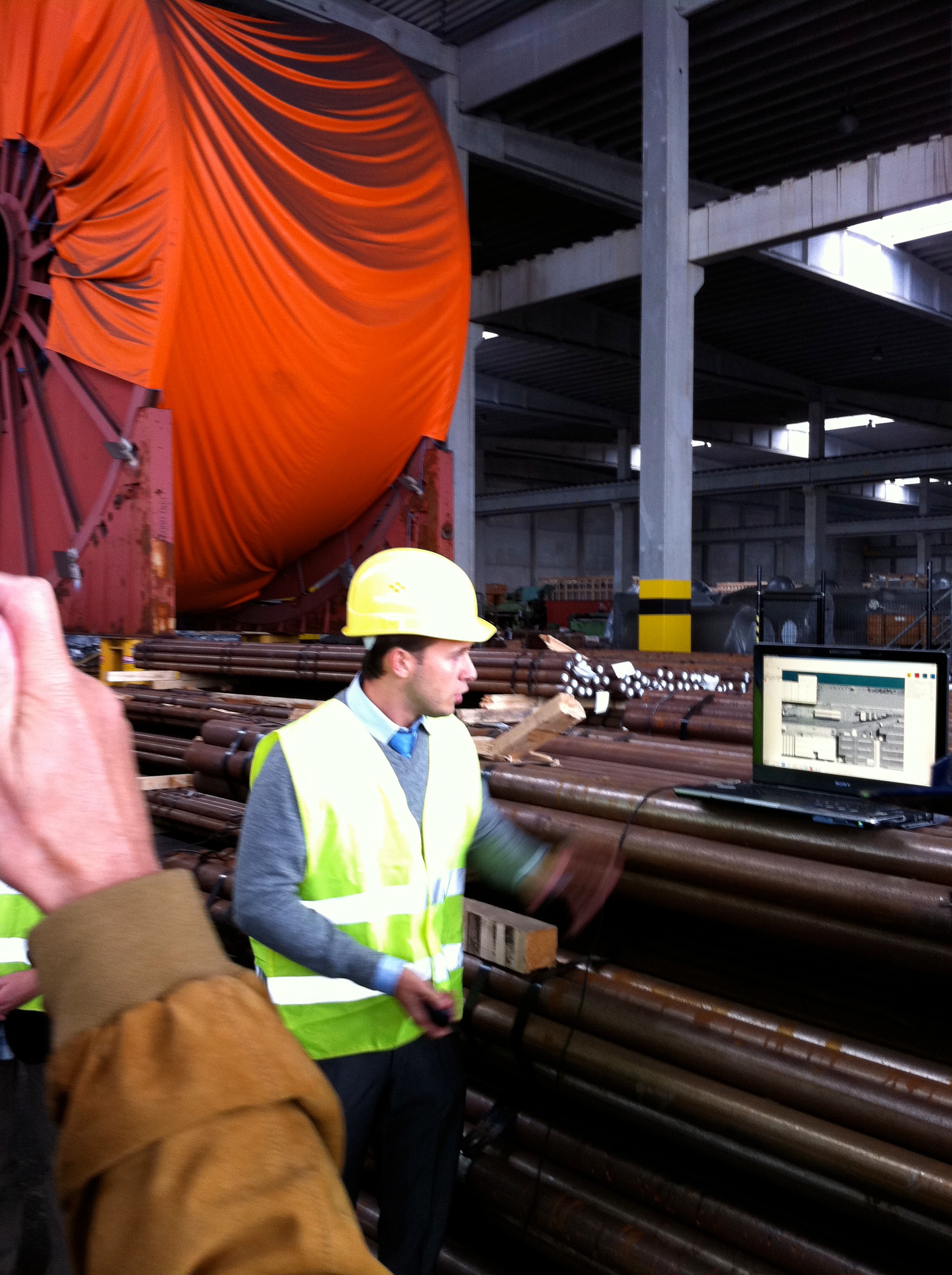
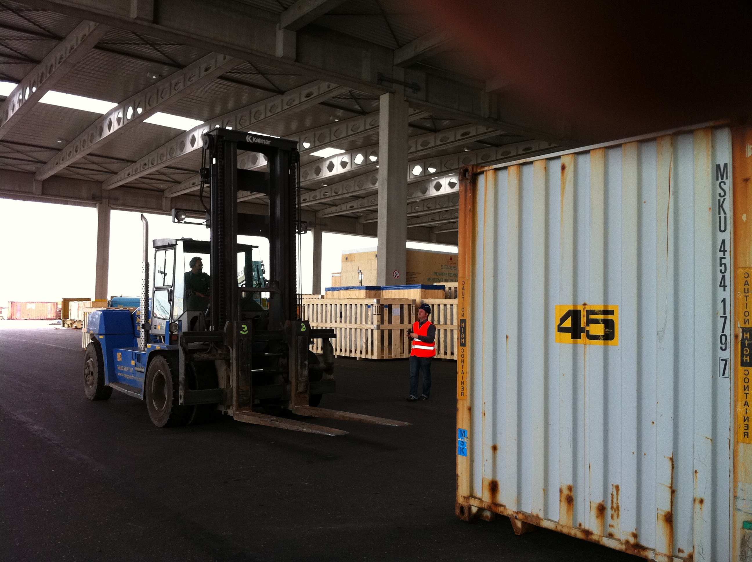
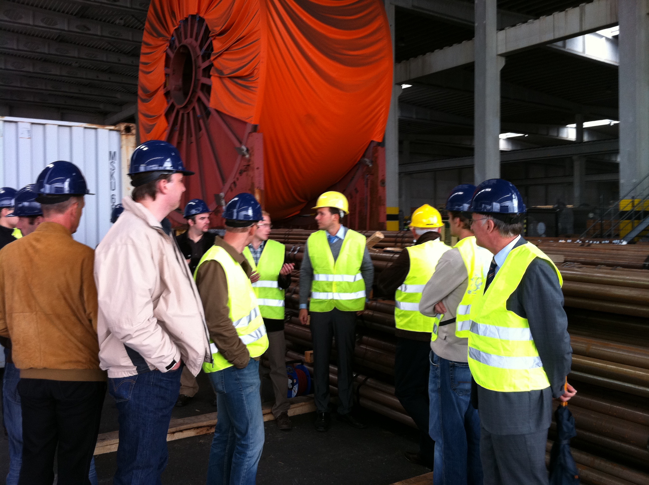
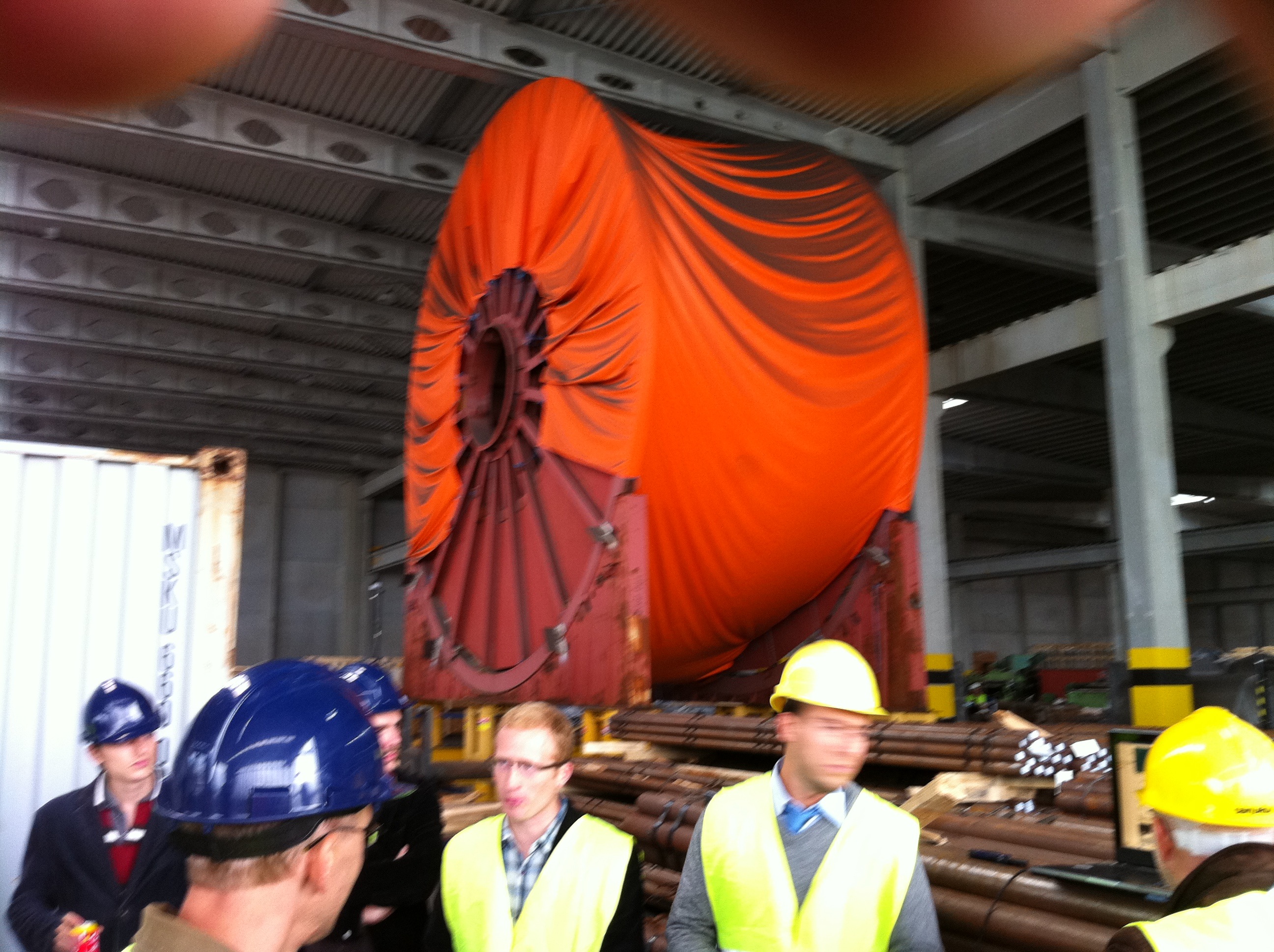
The SCALA (System Convergence in Applications of Location Awareness) project was started 2 years ago and ended this month. Our part in the project was to bring a ZigBee based indoor location system into service and implement it into the SCALA framework. The core framework was designed and implemented by our Belgium colleagues at the university college of Antwerp (Artesis). A major part of the work was done by one of the key researches Jerry Bracke. (Jerry thx for your hard work 🙂 ).
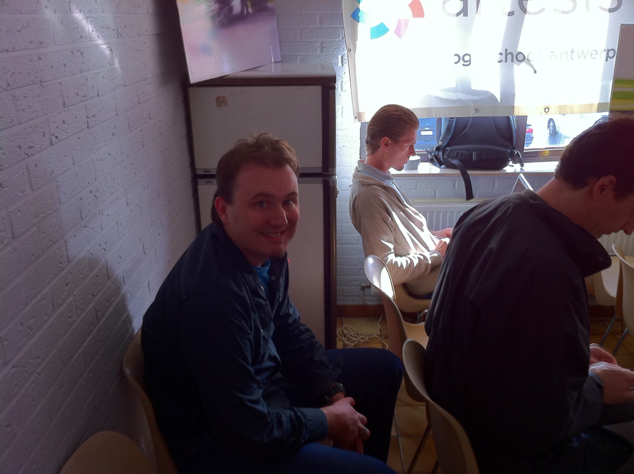
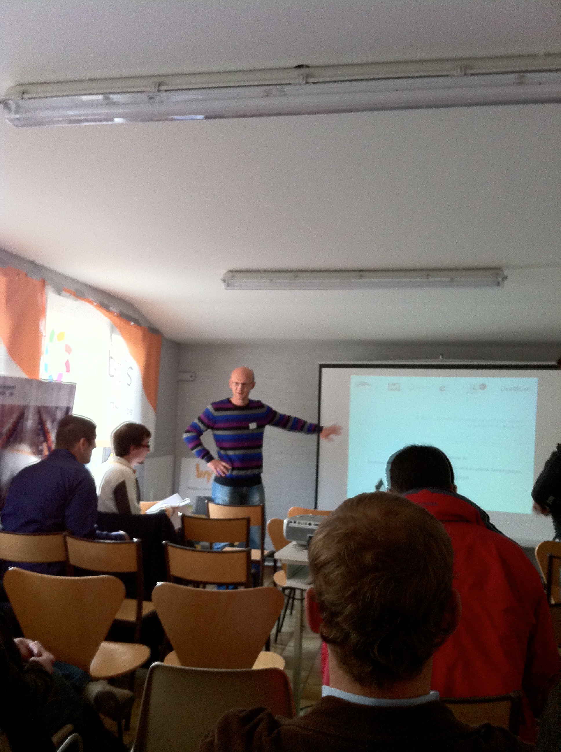
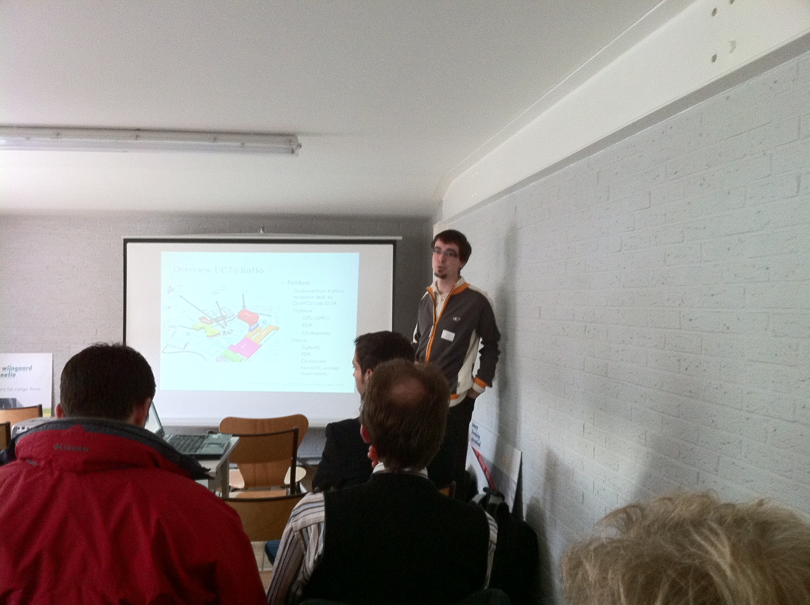
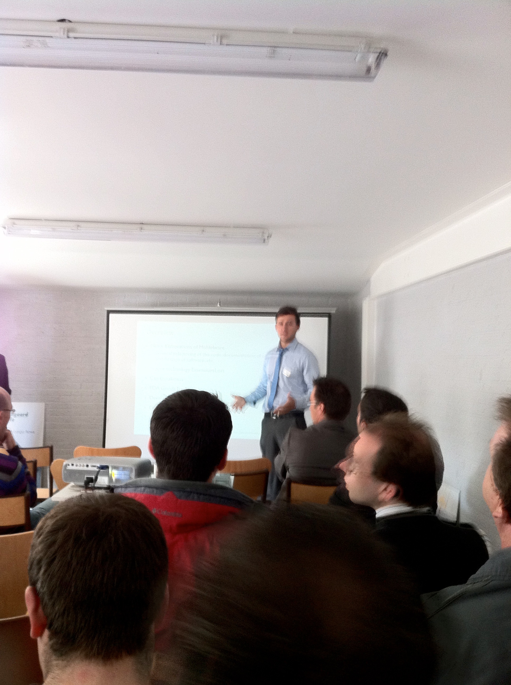
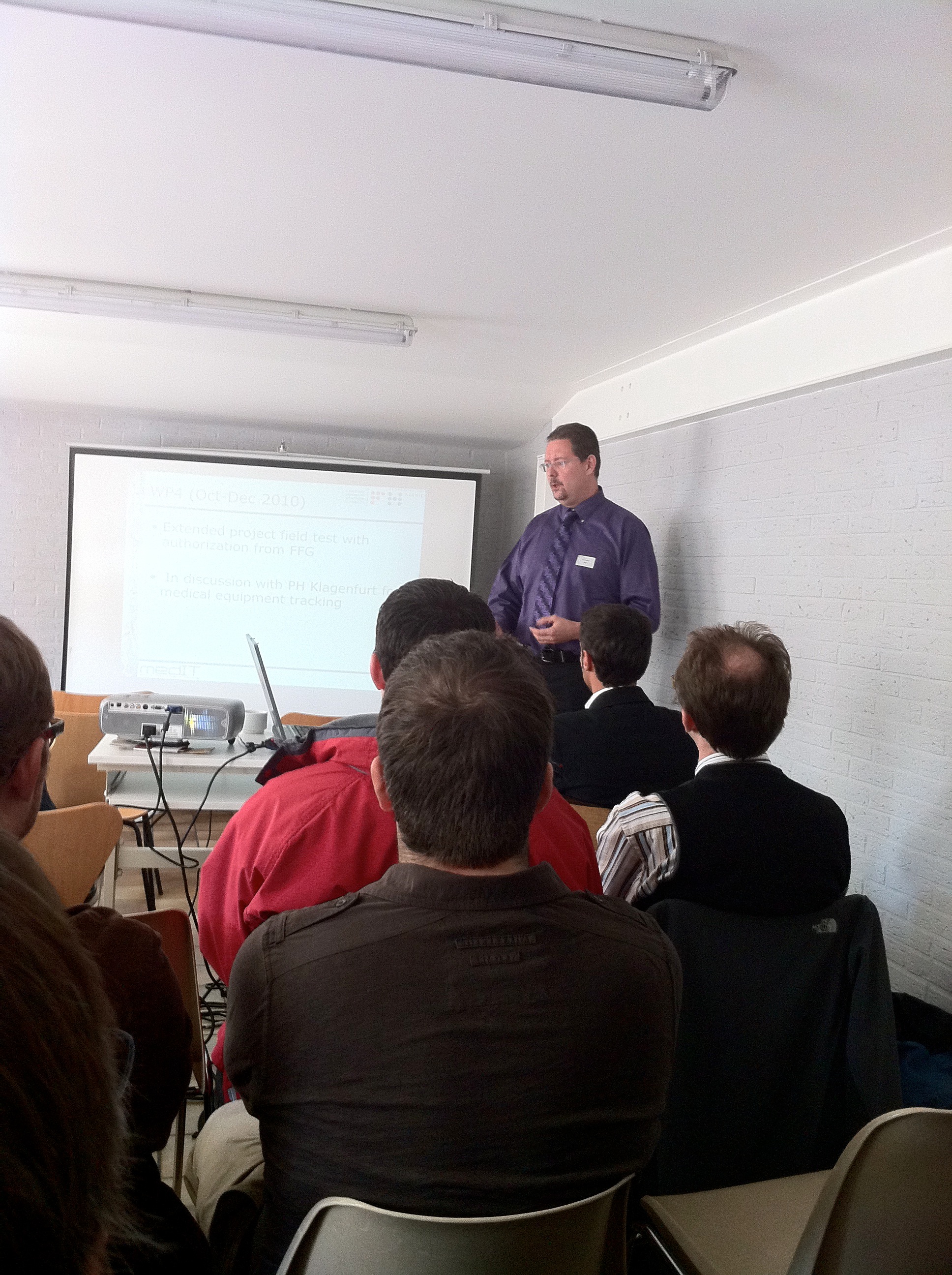
The user commission meeting was hold at the harbor of Antwerp and involves several presentations of the participating universities and companies, also a live demonstration of the SCALA middleware layer was shown.
To get some impressions of the meeting check out the attached image album.
If you are interested into the SCALA project, or want to do some projects in context of Location awareness with ourselves or one of our partners please do not hesitate to contact me.
And the best,……The SCALA middleware layer is open source! 🙂
have fun

Since 2013 CDS 3.1 became Open Source, all source code and pcb layouts are available under the Creative Commons (CC) license.
One of the bigger projects I did the last years (starting 2004) was the CDS (Campus Door System) project. The goal of the project was to build access system mainly focused to the needs of education facilities. The system is designed to work with every RFID reader which can be interfaced via serial protocols. Mostly RS-485 is used because it can be used effectively over long distances and in electrically noisy environments.
Strictly speaking the first prototype of the CDS with raw access control functionality was developed by a student (Christian E. with project lead Helmut W.) – he programmed the first core micro controller functionality.
The new system should be build up from scratch with an new designed PCB (Printed circuit board) which hosts the four main parts of the access system:
The newest version of the CDS v3.x has 16 separate RS-485 bus interfaces and the number of RFID readers is only limited to the used baud rates and because of that the maximum allowed pooling intervals. Version 2.x which is mainly in service has only 8 interfaces.
The bus interface is galvanically isolated from the logic part of the PCB. The RS485 transceivers are mounted through IC sockets.
Since I use devices with serial protocols I needed an UART (Universal asynchronous receiver/transmitter) and in that case I needed 8 respectively 16. The MultiUART should be interfaced through the used micro controllers external data bus. In my case I took the Infineon C167 the battleship amongst the micro controller family.
I learned very fast that digital design for FPGA could be very challenging – ![]() even if you have some sort of asynchronous circuit design. Then you have to deal for example with metastability and other nice stuff concerning signal runtimes 🙂 At that time I was a completely rookie concerning FPGA stuff. I was lucky enough to have a colleague who told me the common mistakes which you could make with FPGA designed. Thanks to Hermann Sterner – you saved me a couple of months 🙂
even if you have some sort of asynchronous circuit design. Then you have to deal for example with metastability and other nice stuff concerning signal runtimes 🙂 At that time I was a completely rookie concerning FPGA stuff. I was lucky enough to have a colleague who told me the common mistakes which you could make with FPGA designed. Thanks to Hermann Sterner – you saved me a couple of months 🙂
In the end I got a stable design with 16 UART designs, every UART could be configured independently. That means for every request to a serial slave the system could set the needed baud rate on the fly. Every UART has a 1024 Byte TX FIFO and a 128 BYTE RX FIFO.
Every UART internally communicates with an Interrupt Controller which notifies the micro controller of new RX events.
Every UART is mapped to an certain location in the higher address space.
As I already mentioned before I used the C167 for the real-time part.  The used C167CR module comes from pytec. With 2MB RAM and 2MB Flash this module has plenty of space for the access tables.
The code which runs on this micro controller is based on the preliminary work of Christian E., the student which developed the first system. In the process of developing I rewrote or adopted a huge part of the code but some parts are still unchanged from the old system and are still in productive use.
The newest version of the access controller is capable to communicate with devices via different protocols and different baud rates. Because of that the protocol stack for the RFID readers is designed modular. The system can easily be adopted for new protocols.
Firmware updates are done through the embedded system (Web interface). At version 3.x the update process does not need a down time for the system. After successfully downloading the firmware to the flash the system switches seamless to the new program code (switch time >100ms).
The whole access system can be administered through a web interface. The used embedded system is the DIMM-PC®/520-IE. I wrote some details about in one of my last posts. As this system only has 32MB RAM and 32MB FLASH I needed an OS which is highly customizable. -> GNU/Linux is the OS of choice 🙂 .
The core elements I used are:
BSP ptxdist powered, for DimmPC (AMD Elan) optimized, Build/Toolchain ready to download.
This part was the most interesting one. Due to the fact that I could not find commercial tools for building embedded GNU/linux OS which suit my needs, I began using open source tools (ptxdist) and build my own toolchains. I learned how to build optimized cross compile toolchains for the used CPUs and in the end I got a highly flexible tool/buildchain for building a whole GNU/Linux with bootloader and all the small things which make the system running 🙂
The embedded system is the core device for administration. Every aspect of the system can be configured through the WEB. All HTTP connections are secured via SSL. The embedded system is holding all persons with there tags, all access rights, all doors respective the RFID readers wired together with access rights in a database system.
The backend of the WEB-Frontend consists of a completely self-written tiny CMS system. Focused to have a very low memory footprint and CPU resources. The initial design of the CDS Web frontend /backend was done by Georg Gut 🙂 thx – well done.
We are using a special patched PHP 3.5.x running one a patched (tuned) apache 1.3.x to get good performance results. with our CMS system.
On every change on the access data the system generates the access tables for the micro-controller system and updates the tables through the SPI interface.
The version before I used the parallel port for transmitting data between DimmPc and micro-controller. But it turns out that this interface was not stable enough, so I decided to change this interface to SPI with 1Mb/s transfer mode.
Feature List:
Check out the gallery for some impressions about the System.
Systems in service: