It all started with a offer on Ebay for a “WIFI-modem for Commodore 64/128” from seller “b********d” (name hidden). I ordered three – as I thought one or the other club member might be interested as well. They were not really cheap, but I thought it is a good idea to support people showing initiative. My bad, I have to say. After many, many weeks of waiting and no single reply on my mails to this seller, opened a Paypal case, won the case, got my money back and decided to set up my own modem. I was (and I am) really upset about such a behaviour of ignorance – such people should be simply thrown out of Ebay.
Jump directly to the firmware download.
Jump directly to the tool download.
My requirements were:
- Compatible with all CBM machines with user port, at least my favourite VIC-20, C64, C128 but if possible also PET computers.
- Proper interfacing, ensure all electrical standards are fulfilled. I don’t want to destroy my valuable old computers.
- Additional features for online gaming (not only BBS connections).
- Small and efficient implementation without unneccesary bells and whistles (low overhead).
Initial research:
I found some projects on the web, which were at the end not what I was looking for.
- Blog of GozdniJezek, who built up a PCB from China from Sven Petersen. Looking at it, I noticed it was not really high integration even using SMD… https://gozdnijezek.medium.com/c64-wifi-modem-user-port-by-sven-petersen-commodore-wifi-modem-21ab0eed411d
- The sources of Sven Petersen were also linked from there: https://github.com/svenpetersen1965/C64-WiFi-Modem-User-Port
- Another example I found was showing exactly the way how not to do it. The ESP modules are not made in a technology to be used for 5V. With some luck, you destroy only the ESP, but if you don’t notice any immediate damage, you may just may kill more of your stuff over time. The website was called …., but I won’t post the URL here. Especially, as a proper solution isn’t really expensive as well, just a little more work.
- There were several others hooking up an ESP module directly to the CBM user port. I had to stop searching, as I couldn’t stand the pain looking at these pages.
Guys, there is a bit more to that than just “high” and “low”… 😀 😀 😀
And just that such “solutions” don’t burn up the modules immediately, they are still not at all safe to use. For me just another very clear example that the internet is full of badly (or not at all) researched information based on wild guesses and sometimes really stupid assumptions without any proof!
But the proof is trivial, if you spend just a few minutes reading. Here is the original datsheet and some reference manual/guide of the chips used on the ESP modules. With no word they mention any 5V tolerance on the I/O pins (which the would of course do if available, as it is a selling feature), but they clearly specify an operating range of ~2.5V to ~3.6V:
https://www.espressif.com/sites/default/files/documentation/0a-esp8266ex_datasheet_en.pdf
https://www.espressif.com/sites/default/files/documentation/esp8266-technical_reference_en.pdf
This Espressif datasheet values are also used in all ESP12 and NodeMCU datasheets I know. A very clear statement about non-5V-compatibility can be found as well, see page 11 of the HW guide below: “The IO of the ESP8266EX is a 3.3 V logic level. In the case of serial communication with a 5 V CMOS logic system, a level switch circuit needs to be added externally.“
All of these NodeMCU (and thus ESP12 modules) I have seen, do not have any level shifters. Here one schematic example: https://raw.githubusercontent.com/nodemcu/nodemcu-devkit/master/Documents/NODEMCU_DEVKIT_SCH.png, but you can simply follow the lines with a ohm-meter yourself. You can measure a series resistor, thats all. There might be modules with levelshifters – who knows – but if a module supports 5V in the I/O – as already mentioned, it will clearly be stated in the module description as added feature (requiring additional parts = bit more expensive modules).
So you can follow some “self-defined experts” in forums or you believe the original datasheets and design guidelines of the experts who made the ICs and need to guarantee its functionality. We are living in a free world, it is up to you and you have been warned… 🙂
So, what I found didn’t really inspire me a lot and I decided to start over again. The information how to use Rx/Tx and RTS/CTS connections on the CBM machines are no secret. One source is e.g. the VC1011 RS232 interface manual from commodore here: http://www.zimmers.net/anonftp/pub/cbm/manuals/peripherals/VIC-1011A_RS-232C_Manual.pdf. This manual provides also some information about how to use the interface on C64 and VIC-20. On top I decided to built up the connections for the UP9600 interfacing used by C64 only as mentioned here: http://www.zimmers.net/anonftp/pub/cbm/documents/projects/rs232/rs232-userport-9600.zip (download at your own risk!) and a reset button. But this was the only bell and whistle I decided to add.
As a general setup, I also wanted to stay with the ESP8266-based modules as many projects did. Firstly, because I did already some experiments with them; Secondly, I could use some Arduino sources from Paul Rickards and Jussi Salin as starting point to ensure the BBS stuff will stay compatible to existing Wifi64 solutions: http://www.mediafire.com/file/tm71a1oa1a3macc/alwyz+modded+firmware.rar (download at your own risk!). Thanks guys for your very good work on the firmware I can use as starting point!
But instead of NodeMCU modules I wanted to use the much smaller ESP12E/F modules and I had to extend the modem firmware with additional features for online gaming.
New module design
The circuitry is still under development and not fully tested – just to tell you, if you plan to re-use this stuff already. Use it at your own risk!
Here is the schematic:

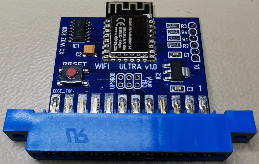
Beside the ESP12 module, there is a 4-way level shifter from TI. This translates the voltages properly from the 3.3V domain of the ESP to the 5.0V domain of the USER port. This reduces the amout of parts needed. A 3.3V regulator supplies the ESP module from the C64. As others on the web already mentioned, one should not draw more than 100mA from the 5V pin of the USER port, my tests came to the result that this is only the case at power-on, where also the inrush currents of the capacitors are seen – which is anyhow a special condition. Otherwise it was always well below.
The rest are usual buffer capacitors and the resistors needed according to the ESP datasheets and schematics like this one: https://docs.ai-thinker.com/_media/esp8266/docs/esp-12f_product_specification_en.pdf. This datasheet also mentions that the max. voltage on I/O pins is 3.6V, hence the level shifters are mandatory.
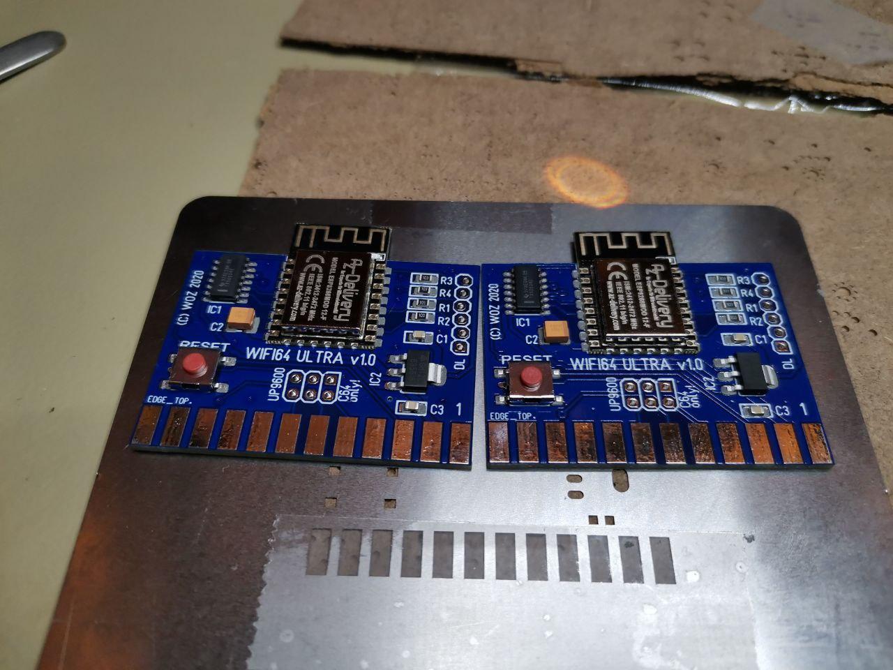
The ESP design guidelines also mentions that 15mm to the left, right and top of the ESP module antenna part should be kept free. So I placed the module the same way as this guideline shows.
An 2.54mm pitch strip connector can be used for flashing the ESP12 firmware. As this is for most users only done once, I didn’t want to spend the effort for adding an USB interface. If required, an USB2serial can be easily added via this connector. But be aware that the C64 must not be connected at the same time! That’s another reason not to implement it, as it avoids any issues with such double-connections by careless users.
Finally, three jumpers to connect the additional user port pins for the UP9600 and the reset switch was added.
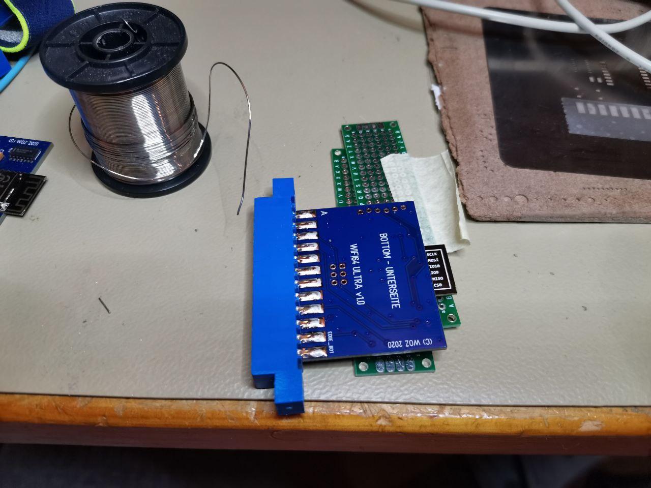
This solution provides a neat and small USER port module, here in 3D view:
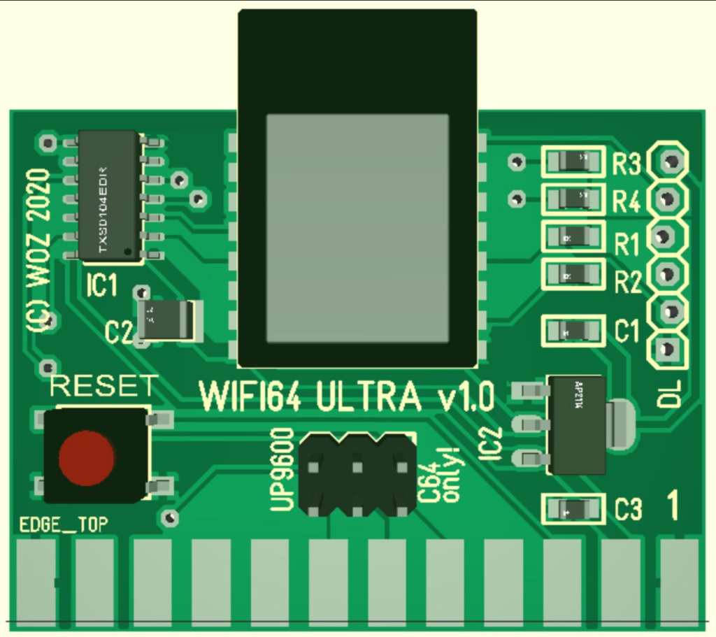
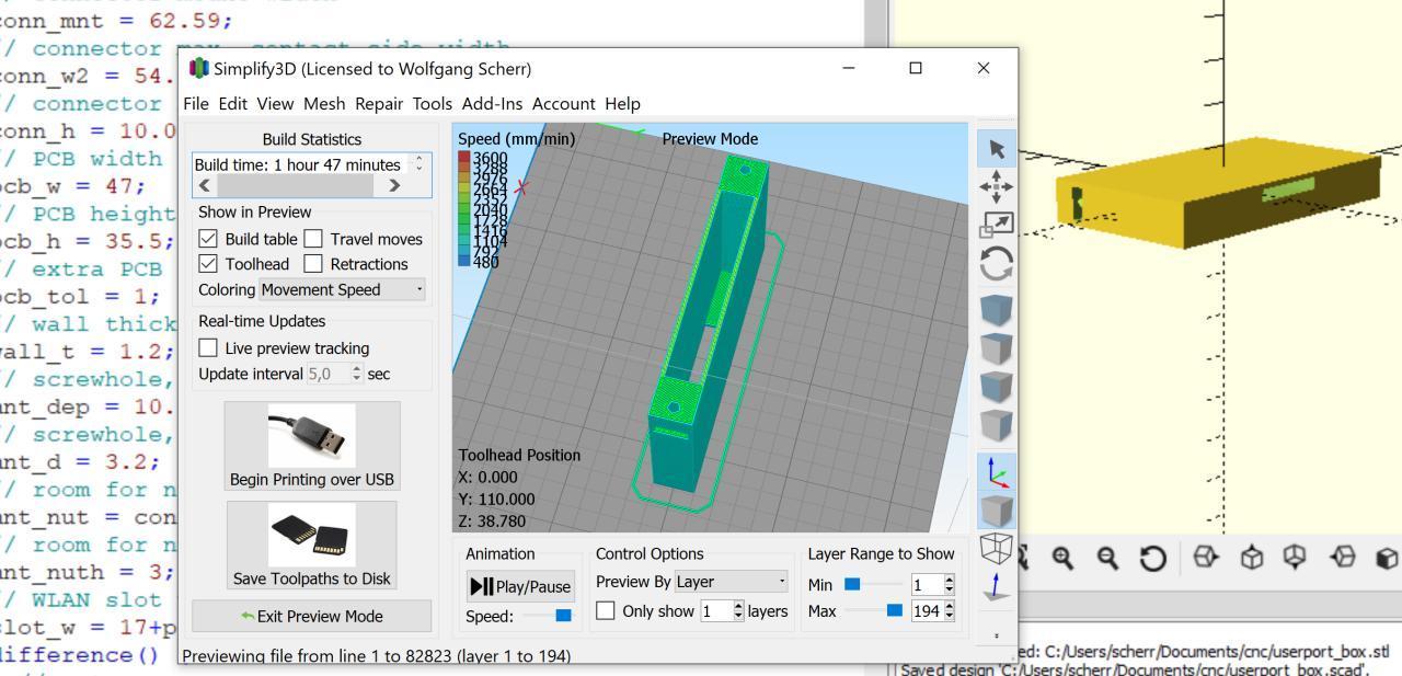
The module case I decided to design in OpenSCAD and implement with my small desktop printer. It is a monlithic case design with an opening for the edge connector and the antenna and can be printed in less than one hour. No need to have an opening for the LED, the case is thin enough to see it very well through the material.
I have no thingiverse & co. account, so I can provide the STL file here – but as you see the design is very simply to set up in half an hour or so…
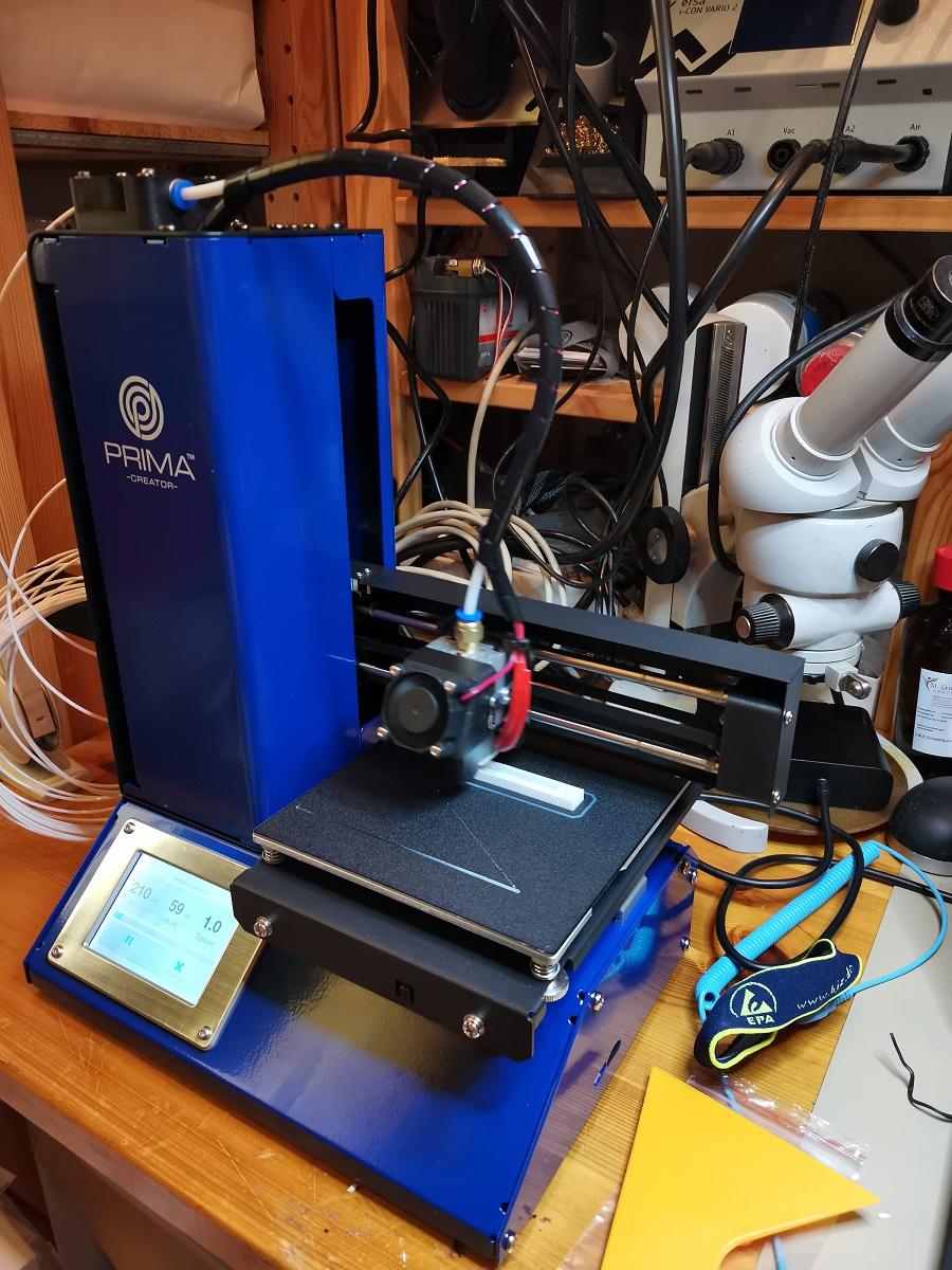
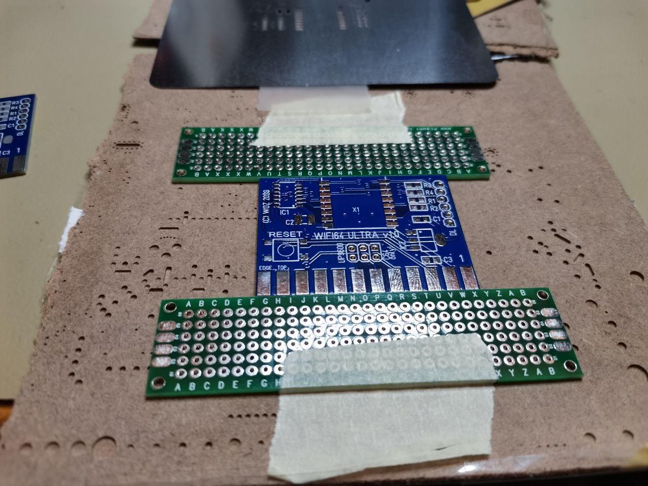
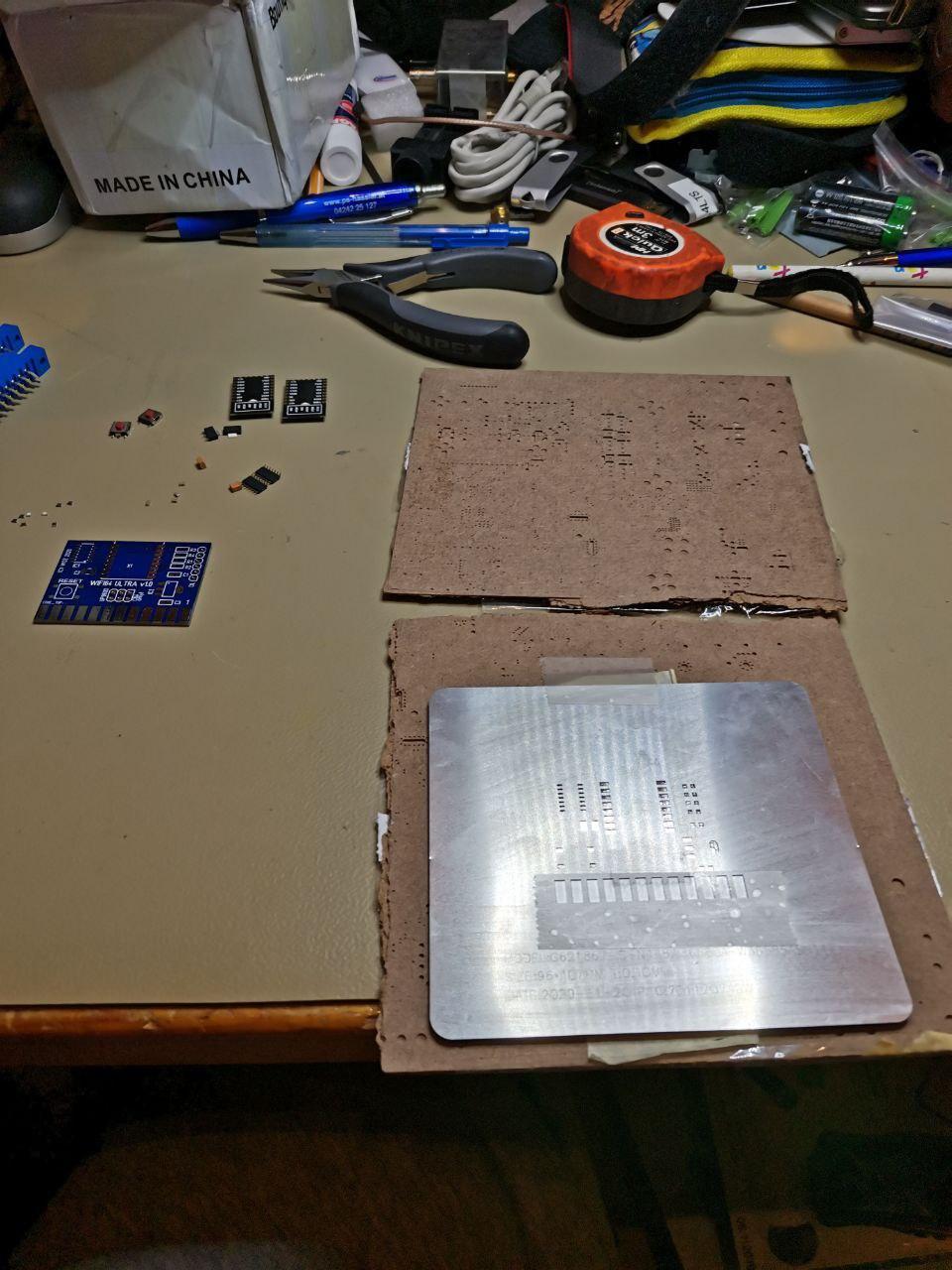
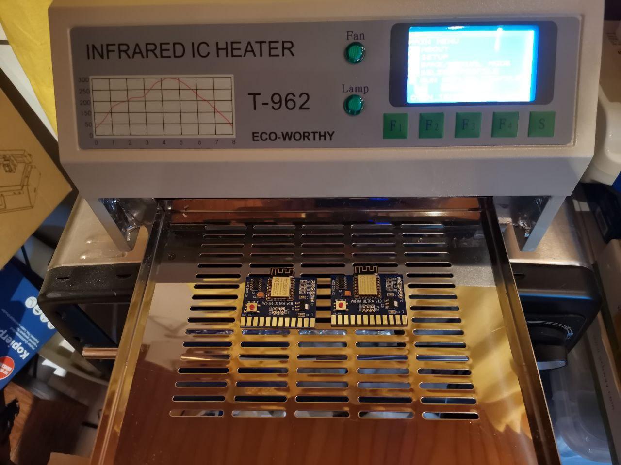
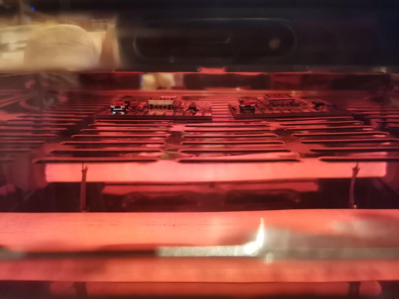
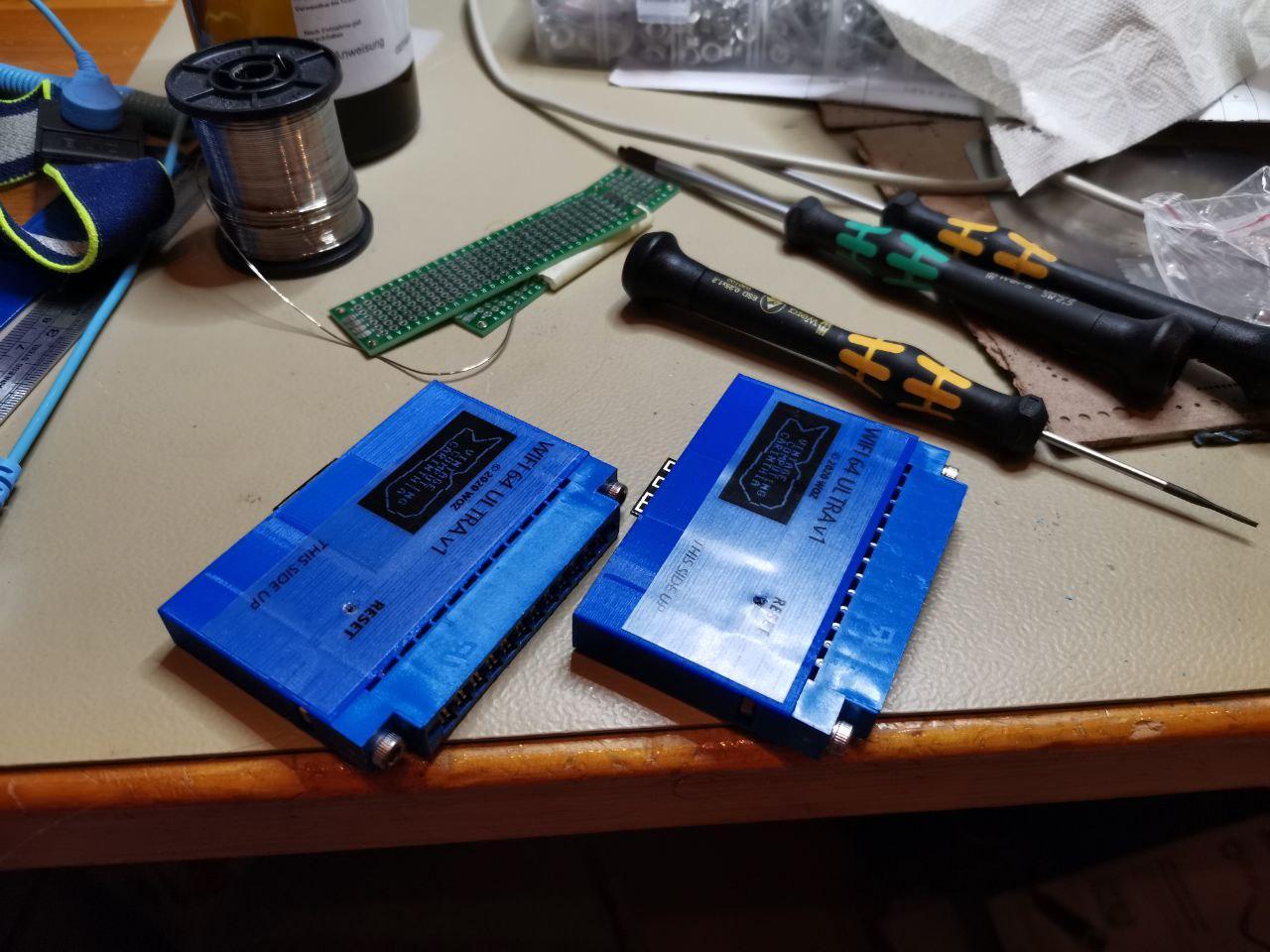
Assembly
Here are some impressions of the production of the first prototypes:


Costs
I didn’t go for a large series of modules, so I didn’t buy many parts and I wanted fast shipping. Of course, if one buys larger volumes and directly from China, better prices are feasible. With Amazon and Ebay I took the most expensive options available, but I got them quite fast. So for now I can set up 5 modules, enough for our VCC club.
Anyhow, it is easy to see that even with a proper electrical setup and expensive web shops, the material costs for one module are still at 12 Euro only!
| Item | Source (base for single pcs. cost) | Cost |
| 1x Case | PRIMA filament, 1kg, incl. shipping | 0,5 € |
| 1x Edge connector | Ebay, 20pcs. incl. shipping | 1,1 € |
| 1x PCB | Pcbway, 11pcs. incl. stencil, shipping | 3,2 € |
| 1x ESP-12F | Amazon, 5pcs. incl. shipping | 4,0 € |
| 1x TXS0104EDR | Mouser, 10pcs. incl. shipping | 1,2 € |
| 1x AP2114H | Mouser, 10pcs. incl. shipping | 0,4 € |
| 4xR, 3xC, 1xSwitch | Mouser | 1,0 € |
| 2x Screw, 2x Nut | No specific shop, M3 | 0,5 € |
| 1x Label | Seiko SLP, transparent | 0,1 € |
| 1x WIFI 64 U | Complete module (parts only) | 12,0 € |
I am not a commercial distributor and my projects are just for fun. But I have a few PCBs left I am willing to give away, in case someone is interested. I can even assemble them semi-professionally, if preferred.
VICE compatible modules
To allow development also on the PC, I also decided to set up a version to be used by emulators like VICE.
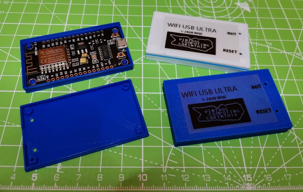
It is based on a blank ESP8266 NodeMCU module in a small 3D printed case. I got this modules without connectors soldered, so I could set up really small modules that way.
| Item | Source (base for single pcs. cost) | Cost |
| 1x Case | PRIMA filament, 1kg, incl. shipping | 0,5 € |
| 1x NodeMCU | Amazon, 5pcs., incl. shipping | 5,5 € |
| 1x WIFI USB | Complete module (parts only) | 6,0 € |
Again, the source for the NodeMCU module I chose is not at all the cheapest, but I didn’t want to wait several weeks to get the material…
Some modules need the USB driver for the CH340 USB chip on some NodeMCU boards, the best source I know is this one: http://www.wch-ic.com/downloads/CH341SER_ZIP.html (external download link for the Windows version – on this site you can also find links to other OS – Mac, Linux, Android – below).
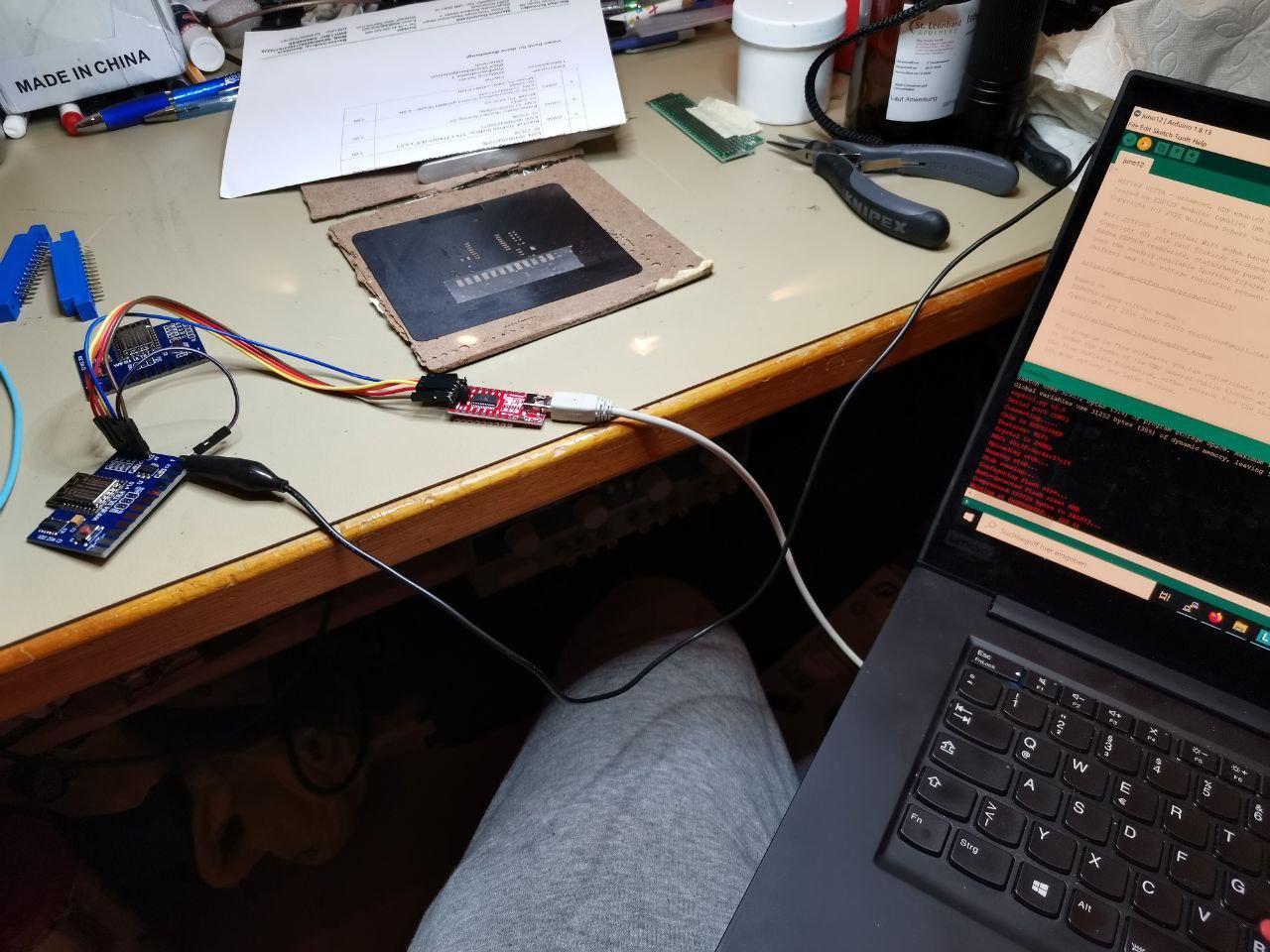
ESP8266 module firmware
Both modules use the same firmware and can be flashed with own tools or using the Arduino environment for ESP boards.
I used Arduino 1.8.13 and the board manager from this URL:
http://arduino.esp8266.com/stable/package_esp8266com_index.json
You can find the modem firmware (including sources according to GPL v3) at csdb.dk and here:
Please note: this firmware is very rudimentary and may contain serious security holes, which could potentially be used to attack also other hosts within your network. A lot of this network routines are “hidden” in the Arduino IDE code and also not visible by the developers, so who knows what can really be done here by evil hackers. As long as you use it within a protected, local network only you should be relatively safe.
Please be aware of that especially if you experiment with other hosts on the unprotected internet. Don’t leave the modem connected when your are not using it. Track your network traffic from time to time to this device to ensure noone else tries to connect it from outside. This are just some basic tipps, you are yourself responsible when operating the modem, noone will give you any guarantees for correct and safe operation. So use it at your own risk!
Accessing the WIFI modem
Commands must start with ‘at’ and end with a linefeed (10 decimal). For the commands itself upper/lowercase characters do not matter. For parameters of content, like for WIFI setup, it might matter. Most important commands are:
.) “at?” … lists all available AT commands
.) “ati” … provides a status of the WIFI/network connection
.) “at&v” … read actual and stored configuration
.) “atz” … restore (stored) configuration from NVRAM
.) “at&w” … store actual configuration to NVRAM
.) “at$ssid=<SSID>” … configures the WIFI SSID (ASCII coding!)
.) “at$pass=<PASSWORD>” … configures the WIFI password (WPA2 is supported, ASCII coding!)
.) “atc0” or “atc1” … disconnect or connect to the wireless LAN network
.) “at$sb=<baudrate>” … set a <baudrate> of 300/600/1200/2400
New commands to control UDP communication are described in a separate chapter below.
Usage on VIC-20 and C64
A basic tool package for C64 and VIC-20 in D64 format is provided at csdb.dk and here:
The module can be used like any other RS232 device available for these machines, either with no or with RTS/CTS handshaking. Please refer to standard literature on operating the modules and descriptions regarding the Wifi64 module.
As soon as a SSID and password is programmed, it will automatically try to connect to the WIFI network. Otherwise you need to set up this first. Be aware that this configuration requires the ASCII character set, but the CBM machines use the PETSCII character set. With the USB module one can use any PC terminal, but the USER port module must be directly configured on the machine. This can give you some headache, given the mentioned character set differences. Some characters are not even available in the same way, like the underscore ‘_’.
This is why the tool package contains a small basic program “wificonf”. It allows to set up the SSID and PASS commands using “DATA” lines of ASCII code. The example configures the SSID ‘test’ with the password ‘PaSs_’, change it accordingly. Furthermore, it allows to set up the target IP/port and own port for communication using the “chatty” program, also found on the tool disk. You may also permanently store the setup in the modem NVM, so it will correctly start up when you switch on your computer (or connect the USB module to your PC).
Based on this program, I also set up a simple terminal program “basterm” you can also find on the tool disk.
Both programs will also run on a VIC-20, please load the programs with “,8” and not with “,8,1” as the start address of the programs are given by the C64.
As mentioned, a chat program called “chatty” allows to send text messages between two machines equipped with Wifi Ultra modems. It uses UTP packages, so delivery is not guaranteed. If you want to use this outside your protected local network, you need to set up UTP port forwarding on your router/firewall at your own risk.
Please note again: Please be aware someone may hack the firmware and gain access to your local network. Do such experiments in the evil internet carefully and don’t leave your connected modem unattended.
Further comments on USB modems with VICE
First, use some PC terminal program (e.g. putty) to check modem communication. Just type “at” there and see you get an “ok”. This way you can check that USB driver and modem are working fine. Otherwise read again the section above how to install the USB driver.
Don’t directly start VICE without knowing you have a proper USB setup and the modem is in principle working on your PC!
The USB modules work nicely with VICE, as long as this is considered:
- VICE may not configure the USB serial interface properly. For example, when programming a NodeMCU module in the Arduino IDE, it is keeping the module in reset afterwards by its control lines. I noticed that VICE does not set up this control lines automatically, so it is a good idea to start any other terminal program (like PUTTY) first and check that the module is responding. Then close the terminal program and open VICE.
- The setup of a COM port is not very well documented for the Windows version. Two parts need to be set up:
.) “Settings” -> “RS232 settings” -> “RS232 userport settings…”:
click on enable, select “RS232 device 1” and set up “300 baud”
.) “Settings” -> “RS232 settings” -> “RS232 settings…”:
set “RS232 device 1” to “comXX” (XX is the port number you can find in the Windows device manager) - I’d recommend to do the testing on VICE with the default 300 BAUD only and try other speeds on the real hardware, where it is possible to switch speeds also during runtime.
- Handling other BAUD rates seems not to be trivial in VICE, as the serial protocol is generated on C64 and VIC-20 by “bit-banging” the user port using kernel routines. So there is no serial device with some data register to simply forward to an USB2serial interface. Thus, switching the BAUD rate during runtime does not work at all in VICE, at least I was not able to do that. The only reliable way is to change the baud rate in an other terminal program, save it permanently in NVM of the modem and configure the same baud rate in VICE. For me this way worked up to 1200 BAUD quite well.
- I was able to access the modem in GTK3VICE-3.3 and WinVICE-3.2, in case of problems, I’d suggest you try these versions first. Others told me that Vice3.4 does not work, I anyhow consider this a beta version not for standard users. Again, if it does not work, download GTKVICE-3.3 or WinVICE-3.2 and use this versions, they are known to work!
- Did I mention to try with Putty on your PC if the modem and USB driver works properly if you have troubles in VICE? You need to separate the problem of a proper PC/USB setup from issues you might have in VICE!
Special ULTRA features
This firmware supports UDP communication. UDP packages are a simple and efficient way to send small packages between two hosts connected on the internet.
The module is able to send UDP packages with up to 260 byte. This allows packages with a 256 block size plus some overhead, like an identification header and a check sum.
Proposal for a common WIFI ULTRA data structure using UDP.

The best strategy to use multi-host communication is to establish a form of token-ring system. A host with the token can communicate to other hosts, then passes the token on.
As the modem is able to fetch data using the HTTP GET protocol, a web server with some simple PHP scripting could be used to retrieve, maintain and distribute host IPs and their ports to set up the UDP network.
UDP modem commands and examples:
