The PmodVGA has 2×8 bit inputs and provides a 12bit RGB VGA interface (4bits each colour) plus corresponding H/V sync signals for most FPGA boards. Especially the newer ZYNQ boards (PYNQ, CORA, ZYBO) do not have VGA anymore on board.
To replace good old arcade coin-op boards in an FPGA, such an analogue output is preferred to operate with the CRT monitors used that time. Resolution is anyhow not that high that the performance of this VGA interface is more than sufficient.
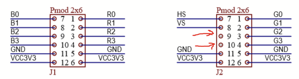
Unfortunately, this adapter has no audio output, which would be nice to have. And it is really a pity, because the second Pmod port J2 has even two pins left (9 and 10), which are connected nowhere. This can be seen in the schematic of the board: https://digilent.com/reference/_media/reference/pmod/pmodvga/pmodvga_sch.pdf.
(Copyright 2016 by Digilent Inc.)
So everything is there to add a stereo pulse-width or pulse-density output for a 3.5mm audio jack!
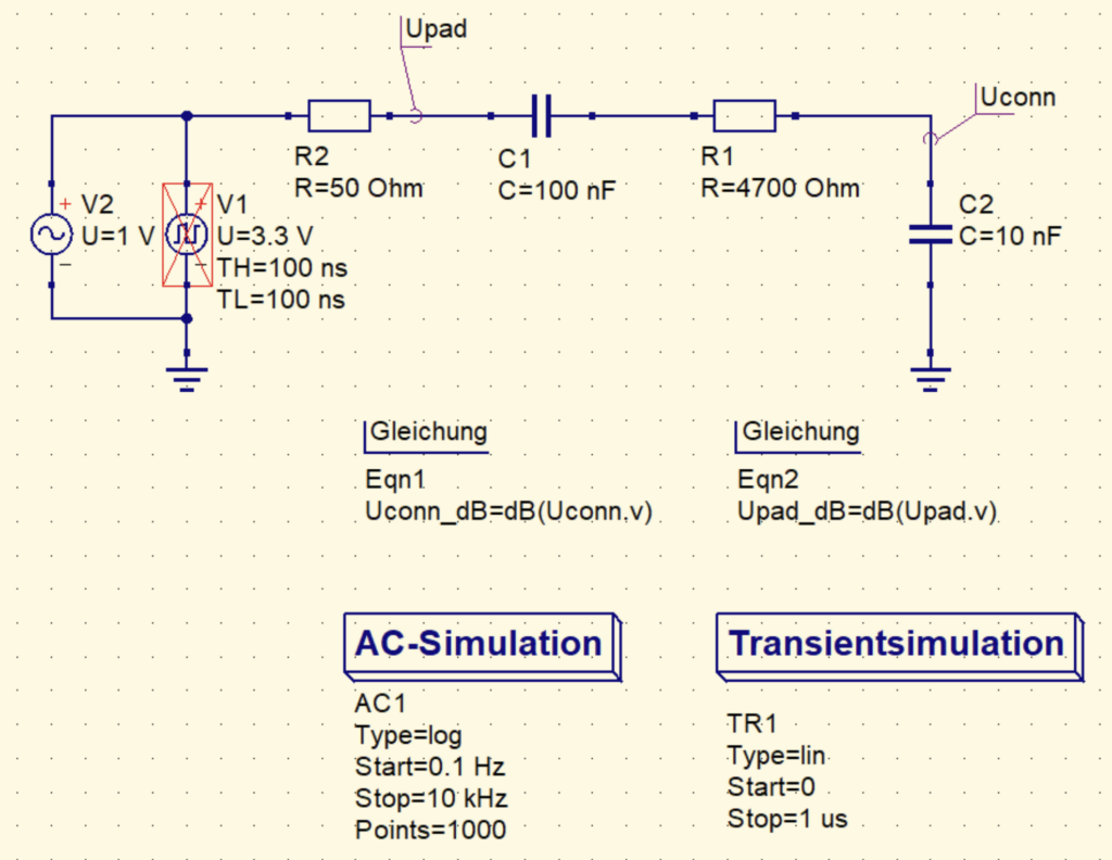
Here you can see the low pass circuit, providing about 3kHz (3dB) corner frequency.
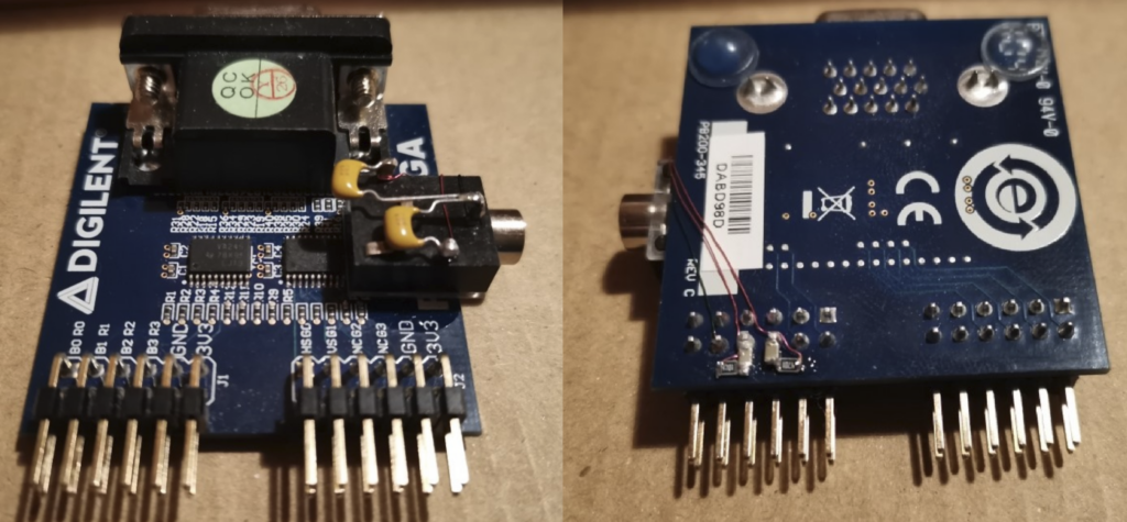
Below you can see my soldering art, the 3.5mm connector is simply glued upside down on the board. The thin wired I used are of course insulated.